Chapter 7
System Configuration
This chapter shows the various System Configuration screens and explains their use
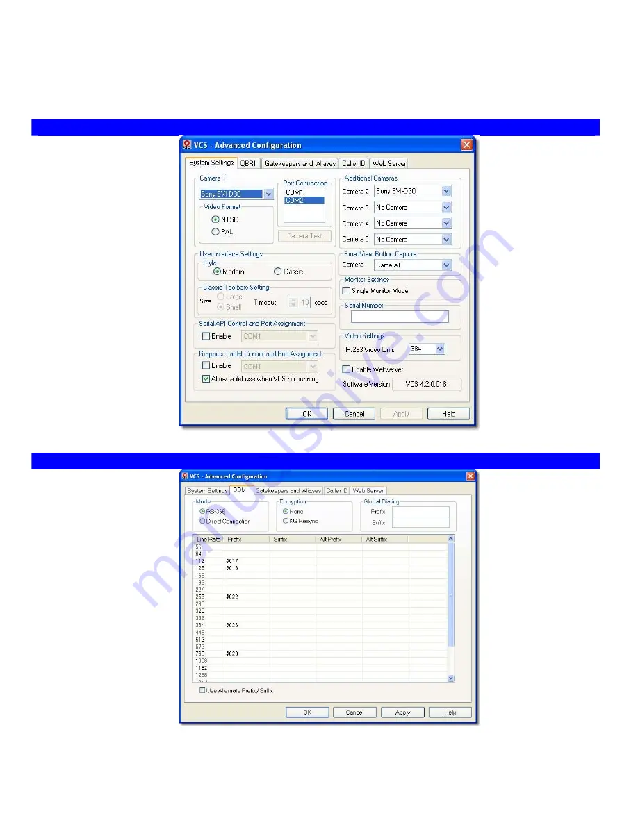
System Settings page
Camera 1
section allows
selection of the camera type,
video format, and the COM port
to be used for serial control.
The [Camera Test] button is
used to verify the serial
connection to the camera.
Note: The [Camera Test] button
will not be active when VCS is
running
.
User Interface Settings
section
allows the selection of the look
and feel of the user interface:
Modern (animated) or
Classic (docking) toolbars.
Serial API Control and Port
Assignment
section allows
configuration of the serial port
for use with custom integration
applications, such as AMX
touch controls.
Graphics Tablet Control and
Port Assignment
section allows
configuration of the serial port
for use with graphics tablets.
Additional Cameras
section allows selection
of additional cameras.
SmartView Button
Capture
section allows
selection of the camera
to be used by the
SmartView function.
Monitor Settings
section
allows the selection of
single or dual monitor
mode.
Serial Number
section
provides a place to type
in the system serial
number.
Video Settings
section
allows setting the upper
limit for H.263 video
utilization.
Enable Webserver:
Check
this box if Soft Tablet is
to be used.
Network Page (for DDM)
Mode
section allows the
selection of RS-366 dialing or
Direct Connection, depending
on the requirements of the
Customer Premise Equipment.
Encryption
section enables
support for an external KG data
encryption device if installed.
Customer Premise Equipment
(IMUX, CSU/DSU, Dialer, etc.)
may require that a prefix or
suffix be appended to the
dialing string to identify the
Line Rate required per call.
Global Dialing
section
allows the user to insert
an additional prefix
and/or suffix. This prefix
and/or suffix will be
appended to every
number dialed. These
may be required,
regardless of the Line
Rate profile used, e.g., to
traverse a PBX, or to
specify a carrier.


