background image

Manual OC32/NG 

VPEB  

Control your Miniature World 


Page 30 of 48 

Version 1.0 – December 15

th

, 2017 

2017 Leon van Perlo  

6


Connecting the I/O Pins 

 
6.1


Selecting the electrical characteristics 


The 32 I/O Pins of the OC32 are subdivided into 4 groups of 8 I/O Pins. The 32 I/O Pins can 
be driven individually and independent of each other. Per group of 8 I/O Pins, the electrical 
properties can be chosen. This is done by placing the right "driver" depending on the required 
properties. A "driver" is an Electronic Module (ADM) or an Integrated Circuit (IC) which has 
to be inserted into a socket on the OC32. This can be done easily by yourself. 
 
On the OC32/NG you will find 4 pairs of IC sockets and 4 pairs of ADM sockets. This may 
depend on the exact version of your OC32. Not all sockets are available on all models. 
Consult your vendor if in doubt. 
 
Per group of 8 I/O Pins, you use either the IC sockets OR the ADM sockets (not both, unless 
in very special cases, not covered in this manual).  
 
When using the IC sockets, you have the following options: 


500mA Sink Driver (TBD62083

4

): This is the default output-type;


500mA Source Driver (TBD62783

3

);


Resistor-array (5V output with integrated resistor); 


Both Sink Driver (TBD62083) and Source Driver (TBD62783) 

The correct place for the drivers on the OC32/NG is depicted in fig 21. 
 

Attention: Source Drivers and Sink Drivers have there own receptacle. Do not 
interchange them because this would cause shortcutting. Resistor arrays have to be 
placed in de Sink Driver receptacle. 
Attention: Using resistor arrays pin 9 and pin 10 (those pins at the largest distance 
from the notch) are left empty. 
 

Note that on the PCB there is text printed to help you indicate the right socket for your 
driver in case you don’t have this document at hand or just to double-check that you are 
using the right socket for the right driver! 
 
ADM modules are “Add-on Driver Modules” that are specifically developed for the OC32/NG. 
OC32-ADM’s can be purchased from the VPEB partners. At the moment the following 
ADM’s are available: 


OC32-ADM/SI: 4.8A 8-port Sink Driver;


OC32-ADM/SO: 4.8A 8-port Source Driver; 


OC32-ADM/MX: 4.8A Multiplexer, 4-port sink + 4-port source; 


OC32-ADM/FH: 4.8A 4-channel Full H-bridge; 

When changing drivers, please observe the following: 


Remove and install drivers only when power is OFF 


Remove IC’s carefully without excessively bending pins 


Install either regular drivers OR ADM’s for the same group of 8 I/O Pins, never both. 
You can select per group of 8 I/O’s if you use a regular driver or an ADM 


When installing an ADM, observe polarization. The ADM has an 8-pin and a 12-pin 
connector and the OC32/NG has 8-pin and 12-pin sockets, so the way the ADM shall 
be installed can be clearly identified. Also doublecheck that the ADM is correctly 
installed (without offset) before applying power. 


4

   The TBD series is a MOSFET driver with a very low Voltage drop. Instead you may use a ‘normal’ 

bipolar driver, being the ULN2803 or equivalent as SINK driver and the UDN2981A or equivalent as 
SOURCE driver, however these may introduce a higher Voltage drop. 

Control your Miniature World   

VPEB  

Manual OC32/NG 

2017 Leon van Perlo 

Version 1.0 – December 15

th

, 2017 

Page 19 of 48 

5


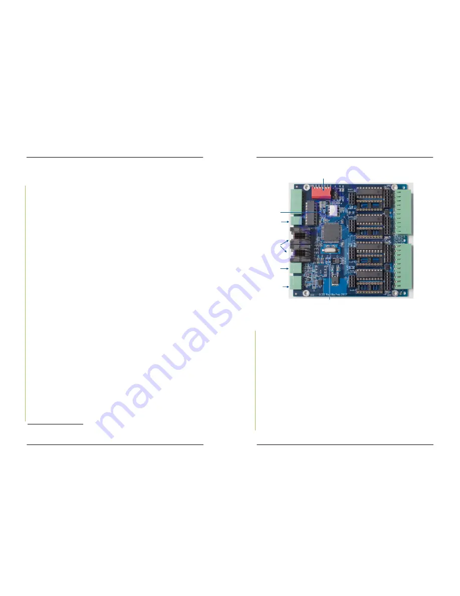
Communicating with the OC32 


Fig 10: OC32 communication connections 


5.1


Ways of communication 


The OC32/NG has 3 communication-interfaces: 


an RS485 communication channel 


an RS232 communication channel 


a DCC interface 

 
The three interfaces are independent and can be used simultaneously, as long as the 
distinct channels don’t receive conflicting commands. 
The RS232 channel and the DCC interface can (seen from the OC32) only receive 
information. The RS485 channel is bidirectional. 
 
In the communication with the OC32, 3 levels can be distinguished: 


Operational: This involves commands that have to do with the situation in which your 
miniature world is in normal operation. Examples are commands for setting a signal or 
switch in a specific state. All communication interfaces can be used for this level. 


Configuration: This involves commands for the configuration of the OC32, for example 
whether an output is to be used for a servo or LED and for setting the parameters for 
servo control. For this level both the RS232 and the RS485 interface can be used. The 
RS485 interface has the advantage here because with this level it is also possible to 
read the settings of the OC32 and therefore gives you the possibility of verification. 

RS485

interface

RS232

interface

Serial Address
Selection

RS485 Termination

DCC Interface

RS485

interface

DCC Low-

Pass Filter

K2A

K2B

K1

K2

K3

K4

K5A

K5B

Содержание OC32/NG

Страница 1: ...r 15 th 2017 2017 Leon van Perlo This page is intentionally left blank Author Leon J A van Perlo Version 1 0 Date December 15 th 2017 OC32 NG Manual VPEBVan Perlo Elektronica Besturingstechniek VPEBVa...

Страница 2: ...y information contained herein may not be copied or distributed in whole or in parts in whatever form without the explicit written approval of the original author The making of copies and prints by us...

Страница 3: ...nctions since all functions are made in software and the OC32 and the OC32 NG run 100 identical software The OC32 NG however integrates the options previously offered by the OC32 DS32 combination and...

Страница 4: ...rivers 500mA TBD62083 31 6 1 2 Source Drivers 500mA TBD62783 31 6 1 3 Sink and Source Drivers TBD62083 TBD62783 32 6 1 4 Resistor Array 5V outputs 32 6 1 5 OC32 ADM SI 4 8A power sink driver 33 6 1 6...

Страница 5: ...array A resistor array is the preferred choice if the input port s are to be activated by a push button or the contacts of a relay A resistor array can also be used if the event input is to be activa...

Страница 6: ...protocol is extremely simple just a few characters for a control command and control is unidirectional The OC32 can send command to the external Device but the external Device cannot send anything ba...

Страница 7: ...ptocoupler between both systems Output Voltage V Rs k 6 1 0 7 5 2 4 9 3 9 12 6 8 15 10 18 12 24 18 Q x GND Extern systeem 4k7 Rs Fig 40 External system with Voltage conversion Table 2 Series resistor...

Страница 8: ...the user So configuration needs to be done through one of the serial interfaces 1 The DCC Interface can also be added afterwards by the user All components needed are through hole so not SMD You need...

Страница 9: ...y goes back into the idle position Take care some relays are polarity sensitive It is important to connect the right pole to Vp and to the OC32 output The power supplied by Vp needs to match the volta...

Страница 10: ...anual OC32 NG 2017 Leon van Perlo Version 1 0 December 15 th 2017 Page 39 of 48 6 4 6 Decouplers OC32 I O Pin OC32 ADM SI 4 8A Sink Driver Solenoids may draw up to 1 5A or more That is too much for th...

Страница 11: ...t SMD types also Fig 28 Connecting LEDs antiparallel in 5V mode Q x 1 Q x Q x 1 Q x Fig 29 Connecting LEDs antiparallel in 500mA mode Vp Rv Q x 1 Q x Rv Vp Rv Q x 1 Q x Rv Fig 30 LEDs on the barriers...

Страница 12: ...n like decouplers turnout coils and motors Below you find a number of examples of devices to be found in the miniature world are presented 6 4 1 LED s with common anode OC32 I O Pin 500mA Sink Driver...

Страница 13: ...Manual OC32 NG 2017 Leon van Perlo Version 1 0 December 15 th 2017 Page 13 of 48 Reset jumper Only used to start the bootloader RS485 Termination jumpers Power jumpers DCC Low pass jumper only with DC...

Страница 14: ...wo power groups on the OC32 NG when using Sink Drivers the number of different power supplies is virtually unlimited The load is connected between the plus pole of the power supply and the output of t...

Страница 15: ...is the GND of the communications port that your PC uses to control the layout The 0V GND as stated above of your miniature world has to be connected to the GND connection of the OC32 All points in fig...

Страница 16: ...nterface is hardly ever needed it has been removed to protect the OC32 from unintended errors Control your Miniature World VPEB Manual OC32 NG 2017 Leon van Perlo Version 1 0 December 15 th 2017 Page...

Страница 17: ...ex situations like 3 LEDs on the barrier of an automatic railroad crossing AHOB which are driven with two outputs and two wires Control your Miniature World VPEB Manual OC32 NG 2017 Leon van Perlo Ver...

Страница 18: ...he examples of section 6 4 There is explained which driver you need for specific types of devices 6 1 1 Sink Drivers 500mA TBD62083 This is the default driver delivered with the OC32 NG module A load...

Страница 19: ...nel Full H bridge When changing drivers please observe the following Remove and install drivers only when power is OFF Remove IC s carefully without excessively bending pins Install either regular dri...

Страница 20: ...PC Table 1 below shows which settings of the dip switch correspond to which address For the record this is the standard numbering starting from 0 If your software starts numbering from 1 onwards you...

Страница 21: ...extended addressing shall also be supported by your software When extended addressing used the address is no longer selected by the DIPswitches but instead by a configuration setting in the OC32 flash...

Страница 22: ...connectors both the one on the OC32 and on the U485 have the same pin layout so pin 1 connects to 1 pin 2 to 2 and if applicable pin 3 to 3 The whole will look like the one below figure 12 Fig 11 Term...

Страница 23: ...al converter is limited and therefore there may be a limitation to the number of modules you can connect this way Up to 10 units should normally work fine If you want to connect more modules than your...

Страница 24: ...ultiple OC32 NG s Other options Of course you can combine options 1 and 2 as described above Since the two RJ45 s and the 3 pole connector are electrically connected effectively every OC32 NG can be u...

Отзывы: