Voyager WVSXC160 Скачать руководство пользователя страница 5

4

Specifications

Model: WVSXC160

FCC ID : 2AHU2WVSXC160

This device complies with Part 15 of the FCC Rules. Operation is subject to the 

following two conditions: (1) this device may not cause harmful interference, and 

(2) this device must accept any interference received, including interference that 

may cause undesired operation.

Notice: 

The changes or modifications not expressly approved by the party responsible 

for compliance could void the user's authority to operate the equipment.

Important Note: 

To comply with the FCC RF exposure compliance requirements, the antenna(s) 

used for this transmitter must be installed to provide a separation distance 

of at least 20 cm from all persons and must not be co-located or operating in 

conjunction with any other antenna or transmitter. No change to the antenna or 

the device is permitted. Any change to the antenna or the device could result in 

the device exceeding the RF exposure requirements and void user’s authority to 

operate the device. 

FEDERAL COMMUNICATIONS COMMISSION INTERFERENCE STATEMENT 

This equipment has been tested and found to comply with the limits for a 

Class B digital device, pursuant to part 15 of the FCC Rules. These limits 

are designed to provide reasonable protection against harmful interference 

in a residential installation. This equipment generates, uses and can radiate 

radio frequency energy and, if not installed and used in accordance with the 

instructions, may cause harmful interference to radio communications. However, 

there is no guarantee that interference will not occur in a particular installation. If 

this equipment does cause harmful interference to radio or television reception, 

which can be determined by turning the equipment off and on, the user is 

encouraged to try to correct the interference by one or more of the following 

measures:

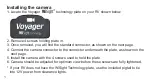
-Reorient or relocate the receiving antenna.

-Increase the separation between the equipment and receiver.

-Connect the equipment into an outlet on a circuit different from that to which the  

 receiver is connected.

-Consult the dealer or an experienced radio/ TV technician for help.
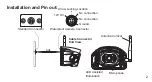
Mounting Type

External type

Image sensor

1/3” CMOS camera

Resolution     

640x480 pixels

Min illumination

0 Lux with IR on

Water resistance    

IP69K

View angle

100°(H), 74°(V), 137°(D) 

Dimension

115.2(W) X 74.6(H) X 71.5(D)mm 

4.53(W) X 2.94(H) X 2.82(D)Inch


Working temperature

-4°F ~ 158°F

Weight      

Approx. 0.3 kg / 0.66 lbs

Содержание WVSXC160

Страница 1: ...WIRELESS COLOR CMOS CAMERA WVSXC160 Features Digital Wireless Technology High Performance CMOS Sensor IR LED low Light Enhancement Waterproof IP69K Wide View Angle Integrated Audio Microphone English...

Страница 2: ...on the next page 4 Connect the camera connector to the connector underneath the plate as shown on the next page 5 Install the camera with the 4 screws used to hold the plate 6 Camera should be adjuste...

Страница 3: ...king Location No connection 12V DC Ground Cable Connector End View Microphone Antenna Vertical LED Assisted Illumination Standard Connector Installation and Pin out No connection Waterproof Camera Con...

Страница 4: ...3 Camera to bracket hardware Specifications Q ty 4 1 Flat Countersunk Head Tapping Screw 8 Allen Wrench...

Страница 5: ...the limits for a Class B digital device pursuant to part 15 of the FCC Rules These limits are designed to provide reasonable protection against harmful interference in a residential installation This...

Страница 6: ...LOR INALAMBRICA CMOS Caracter sticas de WVSXC160 Tecnolog a Digital Inal mbrica Sensor CMOS Alto Rendimiento Mejora Luz LED IR baja Impermeable IP69K Angulo de Visi n Ancho Audio Micr fono Integrado E...

Страница 7: ...en la p gina siguiente 4 Conecte el conector de la c mara al conector debajo de la placa como se muestra en la siguiente p gina 5 Instale la c mara con los 4 tornillos utilizados para sujetar la placa...

Страница 8: ...cha Sin conexi n 12V DC Tierra Vista del Extremo del Conector del Cable Micr fono Antena Vertical Iluminaci n Asistida con LED Conector Est ndar Installation and Pin Out Sin conexi n Conector de C mar...

Страница 9: ...3 Equipo para asegurar c mara a soporte Especificaciones Cant 4 1 Tornillo de cabeza plana avellanado 8 Llave Allen...

Страница 10: ...osici n a RF de la FCC la antena s utilizada para este transmisor debe instalarse para proporcionar una distancia de separaci n de al menos 20 cm de todas las personas y no debe ubicarse ni utilizarse...

Страница 11: ...COULEUR CMOS SANS FIL Caract ristiques WVSXC160 Technologie num rique sans fil Haute performance CMOS Am lioration faible lumi re LED IR Imperm able IP 69K Angle de Vue Large Microphone Audio int gr...

Страница 12: ...ur la page suivante 4 Connectez le connecteur de la cam ra au connecteur sous la plaque comme indiqu sur le page suivante 5 Installez la cam ra avec les 4 vis utilis es pour maintenir la plaque 6 La c...

Страница 13: ...du verrou Pas de connexion 12V DC Mise la terre Vue lat rale du connecteur pour c ble Microphone Antenne verticale clairage DEL assist Connecteur standard Installation et Montage Pas de connexion Conn...

Страница 14: ...3 Cam ra au mat riel de support Caract ristiques Qt 4 1 Vis taraudage t te plate 8 Cl Allen...

Страница 15: ...ition RF de la FCC l les antenne s utilis e s pour cet metteur doit vent tre install e s pour fournir une distance de s paration d au moins 20 cm de toutes les personnes et ne doit vent pas tre co loc...

Страница 16: ...aract ristiques et sp cifications peuvent tre modifi es Caracter sticas y especificaciones sujetas a cambios sin previo aviso For further technical support call Pour toute assistance technique plus d...

Отзывы: