


UNIFREM v.3.41x
10 May 2017
Page 106 from 180
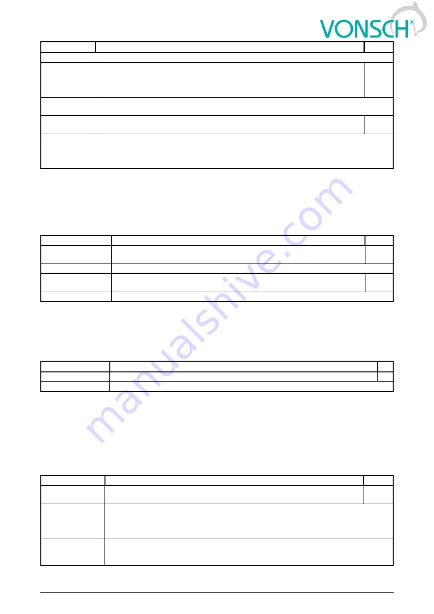
Name [ID]
Description
Def.
500,0 °C
average temperature from the multiple measuring points.
Low
ETP
temperature
[1283]
When ETP temperature drops below this value, converter generates a fault E38-
ETP temperature (page 33) because of the extremely low temperatures, which
can be caused by incorrect wiring or damage of ETP sensor. When ETP Type set
to "PTC thermistor", this parameter has no meaning.
-100,0
°C
-
500,0
°C
÷
500,0 °C
ETP
maximal
current [1087]
Maximal ETP measuring current.
10,00
mA
0,01 mA ÷ 20,00
mA
Restricts the current to the EHP sensors to prevent undesired overheating of the sensor. If
a special sensor is used, it is necessary to set the maximal current according to its
specification. In the EHP = PTC type, the measuring current is limited to the 1mA value and
in the PT100 type to 3mA and then this parameter is inactive.
CUSTOM SENSOR
Group of parameters number [810]
Setting the characteristic of the custom ETP sensor (if "Custom sensor" is selected in ETP Type [861] (page
105)).
MENU \ SETTINGS \ FUNCTIONS \ EXTERNAL THERMAL PROTECTION (ETP) \ CUSTOM SENSOR
Name [ID]
Description
Def.
Resistance by 20°C
[863]
Resistance value of an external temperature sensor in 20°C, in case that the
sensor characteristics is user-defined.
1200,0
Ω
0,1 Ω ÷ 99000,0 Ω
Resistance in 100°C
[864]
Resistance value of an external temperature sensor in 100°C, in case that the
sensor characteristics is user-defined.
4600,0
Ω
0,1 Ω ÷ 99000,0 Ω
SPECIAL SETTING ETP
Group of parameters number [569]
Special source setting for the ETP voltage drop measurement.
MENU \ SETTINGS \ FUNCTIONS \ EXTERNAL THERMAL PROTECTION (ETP) \ SPECIAL SETTING ETP
Name [ID]
Description
Def.
U ETP Signal [857]
Selecting the signal, which should be evaluated as voltage on the ETP sensor.
-
Signal
Usually an analog input in the 0 to 10 V mode is used.
7.7.8 IRC1,2 DIFFERENCE
Group of parameters number [1081]
Setting the IRC1 and IRC2 encoders frequency difference operation. Encoder IRC difference is used to
adapt the behaviour of multi-motor drive during unequal speed of single motors caused by external
influences. For example, the front and rear axle traction vehicle. The value of Freq. IRC1-IRC2 gear [1086]
(page 19) is calculated as the absolute value of the difference of the absolute values of the quantities Freq.
IRC1 [434] (page 19) and Freq. IRC2/ARC [803] (page 19).
MENU \ SETTINGS \ FUNCTIONS \ IRC1,2 DIFFERENCE
Name [ID]
Description
Def.
IRC1,2 Detuning
[1082]
Setting the operation method and the converter operation when detuning the
IRC1 and IRC2 speed.
□ Torque limitation
After exceeding the minimal limit if the IRC1 and IRC2 frequency difference Minimal
IRC1,2 difference [1084] (page 107), the motor torque will start to be limited and at the
maximal difference Maximum IRC1,2 difference [1085] (page 107), the torque will be
limited to zero.
□ Reset PWM
After exceeding the maximal limit if the IRC1 and IRC2 frequency difference Maximum
IRC1,2 difference [1085] (page 107), PWM RESET will be generated and at the minimal
difference Minimal IRC1,2 difference [1084] (page 107), operation is permitted again.
Содержание Quatrofrem Series
Страница 2: ...UNIFREM v 3 41x 10 May 2017 Page 2 from 180...
Страница 127: ...UNIFREM v 3 41x 10 May 2017 Page 127 from 180...


