VONROC MS501AC Скачать руководство пользователя страница 9

EN

9

WWW.VONROC.COM

objects that can make a connection from one 
terminal to another.

 Shorting the battery termi-

nals together may cause burns or a fire.

d)   

Under abusive conditions, liquid may be ejected 
from the battery; avoid contact. If contact acci-
dentally occurs, flush with water. If liquid contacts 
eyes, additionally seek medical help. 

Liquid ejec-

ted from the battery may cause irritation or burns.

e)

   Do not use a battery pack or tool that is dama-

ged or modified.

 Damaged or modified batteries 

may exhibit unpredictable behaviour resulting 
in fire, explosion or risk of injury.

f)

   Do not expose a battery pack or tool to fire 

or excessive temperature.

 Exposure to fire or 

temperature above 130 °C may cause explo-
sion. NOTE The temperature „130 °C“ can be 
replaced by the temperature „265 °F“.

g)

   Follow all charging instructions and do not 

charge the battery pack or tool outside the 
temperature range specified in the instructi-
ons. 

Charging improperly or at temperatures 

outside the specified range may damage the 
battery and increase the risk of fire.

6)   Service

a)  

Have your power tool serviced by a qualified 
repair person using only identical replacement 
parts.

 This will ensure that the safety of the 

power tool is maintained.

b)

   Never service damaged battery packs.

 Service 

of battery packs should only be performed by the 
manufacturer or authorized service providers.

SPECIFIC SAFETY INSTRUCTIONS

• 

Mitre saws are intended to cut wood or wood-li-
ke products, they cannot be used with abrasive 
cut-off wheels for cutting ferrous material such 
as bars, rods, studs, etc.

 Abrasive dust causes 

moving parts such as the lower guard to jam. 
Sparks from abrasive cutting will burn the lower 
guard, the kerf insert and other plastic parts.

•  

Use clamps to support the workpiece whenever 
possible. If supporting the workpiece by hand, 
you must always keep your hand at least 100 mm 
from either side of the saw blade. Do not use this 
saw to cut pieces that are too small to be secure-
ly clamped or held by hand.

 If your hand is placed 

too close to the saw blade, there is an increased 
risk of injury from blade contact.

•  

The workpiece must be stationary and clamped 
or held against both the fence and the table. 
Do not feed the workpiece into the blade or cut 

“freehand” in any way.

 Unrestrained or moving 

workpieces could be thrown at high speeds, 
causing injury.

•  

Push the saw through the workpiece. Do not 
pull the saw through the workpiece. To make a 
cut, raise the saw head and pull it out over the 
workpiece without cutting, start the motor, press 
the saw head down and push the saw through 
the workpiece.

 Cutting on the pull stroke is likely 

to cause the saw blade to climb on top of the 
workpiece and violently throw the blade assem-
bly towards the operator.

•  

Never cross your hand over the intended line of 
cutting either in front or behind the saw blade.


Supporting the workpiece “cross handed” i.e. 
holding the workpiece to the right of the saw 
blade with your left hand or vice versa is very 
dangerous.

•  

Do not reach behind the fence with either hand 
closer than 100 mm from either side of the saw 
blade, to remove wood scraps, or for any other 
reason while the blade is spinning.

 The proximity 

of the spinning saw blade to your hand may not 
be obvious and you may be seriously injured.

•  

Inspect your workpiece before cutting. If the 
workpiece is bowed or warped, clamp it with the 
outside bowed face toward the fence. Always 
make certain that there is no gap between the 
workpiece, fence and table along the line of the 
cut.

 Bent or warped workpieces can twist or 

shift and may cause binding on the spinning saw 
blade while cutting. There should be no nails or 
foreign objects in the workpiece.

•  

Do not use the saw until the table is clear of all 
tools, wood scraps, etc., except for the workpie-
ce.

 Small debris or loose pieces of wood or other 

objects that contact the revolving blade can be 
thrown with high speed.

•  

Cut only one workpiece at a time.

 Stacked multi-

ple workpieces cannot be adequately clamped or 
braced and may bind on the blade or shift during 
cutting.

•  

Ensure the mitre saw is mounted or placed on a 
level, firm work surface before use.

 A level and 

firm work surface reduces the risk of the mitre 
saw becoming unstable.

•  

Plan your work. Every time you change the bevel 
or mitre angle setting, make sure the adjustable 
fence is set correctly to support the workpie-
ce and will not interfere with the blade or the 
guarding system.

 Without turning the tool “ON” 

and with no workpiece on the table, move the 
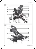
Содержание MS501AC

Страница 1: ...SLIDING MITRE SAW MS501AC EN Original Instructions 07 DE bersetzung Der Originalbetriebsanleitung 19 NL Vertaling van de oorspronkelijke gebruiksaanwijzing 33 FR Traduction de la notice originale 46...

Страница 2: ...WWW VONROC COM 2 A 1 2 3 4 5 6 7 8 9 12 13 11 20 17 18 16 15 10 8 12 19 9 10 11 14 27 26 25 24 23 22 21 7 B 2 3 46 38 37 36 27 28 29 24 21 30 33 32 12 31 34 35...

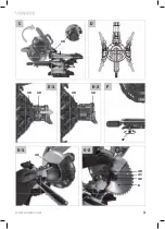
Страница 3: ...WWW VONROC COM 3 C 38 D F 37 E 1 30 39 E 2 30 39 G 1 40 G 2 40 41 42 6...

Страница 4: ...WWW VONROC COM 4 G 3 43 G 4 6 H 35 44 21 10 33 34 I J 7 6 K...

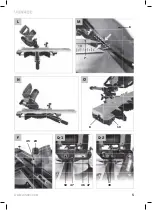
Страница 5: ...WWW VONROC COM 5 M N O 10 8 P 24 45 Q 2 48 Q 1 18 46 47 47 L 6 7...

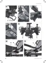
Страница 6: ...WWW VONROC COM 6 T W X S U R 32 50 49 31 V 51 51 26 28 28...

Страница 7: ...ns of the reducer are suitable for the base blade thickness and the saw blade hole diameter as well as the tool spindle diameter Wherever possible use the reducers provided with the saw blade The saw...

Страница 8: ...complacent and ig nore tool safety principles A careless action can cause severe injury within a fraction of a second 4 Power tool use and care a Do not force the power tool Use the correct power too...

Страница 9: ...ed or held against both the fence and the table Do not feed the workpiece into the blade or cut freehand in any way Unrestrained or moving workpieces could be thrown at high speeds causing injury Push...

Страница 10: ...sk of injury Keep your work area clean Material mixtures are particularly hazardous Light metal dust may catch fire or explode Do not use dull cracked bent or damaged saw blades Unsharpened or imprope...

Страница 11: ...ameter Base blade thickness Width of cut Bore diameter Number of teeth 216 mm 1 6 mm 2 8 mm 30 mm 40T Saw capacity height x width Mitre 0 Bevel 0 Mitre 0 Bevel 45 Mitre 45 Bevel 0 Mitre 45 Bevel 45 65...

Страница 12: ...downwards slightly 2 Pull the position lock knob 38 fully outwards and lock it in place by turning it 3 Slowly move the handle 2 upwards Locking the transport position transport position Before locki...

Страница 13: ...ective guard 5 must cover the entire saw blade 6 automatically Replacing the saw blade fig G Before carrying out any work on the machine disconnect the mains plug from the power supply When mounting t...

Страница 14: ...ked by dust chips or fragments of the workpiece Thus it must be cleaned regularly To do so 1 Disconnect the mains plug from the power supply 2 Wait until the saw blade has come to a complete stop 3 Re...

Страница 15: ...rotate the table 11 left or right to the desired preset The angle can be read on the scale for mitre angle 16 using the indicator for mitre angle 17 3 Release the lever The lever must be felt to enga...

Страница 16: ...e fence 35 and the saw blade 6 is 8mm as shown on figure M Make sure the fence does not touch the blade 3 Firmly clamp the workpiece Ensure the work piece clamp is placed on the right side 4 Turn on t...

Страница 17: ...en the retaining screw Fine tuning the 45 bevel angle Fig R T 1 Adjust the mitre and bevel angle to 45 2 Lower the handle 2 and secure it using the position lock knob 38 3 Lock the slide movement usin...

Страница 18: ...19 EU for Waste Electrical and Electronic Equipment and its implementation into national right power tools that are no longer usable must be collected separately and disposed of in an environmentally...

Страница 19: ...ch Das Produkt entspricht den geltenden Sicherheitsnormen der europ ischen Richtlinien 1 2 3 Beim S gen von Gehrungswin keln muss die verstellbare Anschlagschiene nach au en gezogen werden 30mm max 21...

Страница 20: ...Tragen Sie pers nliche Schutzausr stung und immer eine Schutzbrille Das Tragen pers nI icher Schutzausr stung wie Staubmaske rutschfeste Sicherheitsschuhe Schutzhelm oder Geh rschutz je nach Art und E...

Страница 21: ...hl ssel N gel Schrauben und anderen kleinen Metallobjekten fernzuhalten die eine Verbindung zwischen den Polen bilden k nnen Kurzschlie en der Pole kann Brand oder Verbrennungen verursachen d Bei fals...

Страница 22: ...n Verwenden Sie die S ge erst wenn der Tisch frei von Werkzeugen Holzabf llen usw ist nur das Werkst ck darf sich auf dem Tisch befinden Kleine Abf lle lose Holzst cke oder andere Gegenst nde die mit...

Страница 23: ...eingebauten Laser nicht gegen einen Laser anderen Typs aus Von einem nicht zu diesem Elektrowerkzeug passenden Laser k nnen Gefahren f r Personen ausgehen Entfernen Sie niemals Schnittreste Holzsp ne...

Страница 24: ...rungsschnitt 45 Schr gschnitt 45 65 x 340 mm 38 x 340 mm 65 x 240 mm 38 x 240 mm Minimale Werkst ckabmessungen 3 x 10 mm Laser Spezifikationen Klasse Wellenl nge Leistung 2 650 nm 1 mW Klasse 2 Wellen...

Страница 25: ...verriegelungsknopf 38 erleichtert das Bewegen des Elektrowerkzeugs beim Transport zu verschiedenen Arbeitsorten Entriegeln der Transportposition Arbeitsposition 1 Dr cken Sie den Griff 2 etwas nach un...

Страница 26: ...39 wieder fest Drehen Sie den vorderen Kippschutz 37 wie in Abbildung F gezeigt nach innen oder au en bis das Elektrowerkzeug waagerecht auf der Arbeitsfl che steht berpr fen der Schutzabdeckung Abb...

Страница 27: ...au erdem sicher dass der Klemmflansch mit der konvexen Seite nach au en montiert ist 6 Montieren Sie die Klemmschraube 42 und dre hen Sie sie mit dem Inbusschl ssel w hrend Sie gleichzeitig die Spind...

Страница 28: ...Gewindestange der Werkst ck klemme 21 fest an um das Werkst ck zu fixieren Zum L sen lockern Sie einfach die Gewindestange der Werkst ckklemme 21 Mit dem Knopf f r die Werkst ckklemme 44 l sst sich d...

Страница 29: ...hine ein Warten Sie bis das S geblatt die volle Drehzahl erreicht hat 5 Bewegen Sie nun den Griff langsam nach unten so dass das S geblatt das Werkst ck durchsch neidet und durch den Schlitz im Tisch...

Страница 30: ...F hren Sie den Werkzeugarm langsam mit dem Griff nach unten dr cken Sie anschlie end den Griff 2 in Richtung Anschlag 9 und s gen Sie das Werkst ck mit gleichm igem Vorschub durch Bei kleinen Werkst c...

Страница 31: ...dem Positionsverriegelungsknopf 38 3 Blockieren Sie die Schlittenbewegung mit der Sicherungsschraube f r die Gleitschienen 29 4 Stellen Sie einen Winkelmesser auf 90 ein und legen Sie ihn auf den Tis...

Страница 32: ...Stellen abgegeben werden Nur f r EG L nder Entsorgen Sie Elektrowerkzeuge nicht ber den Hausm ll Entsprechend der EU Richtlinie 2012 19 EG ber Elektro und Elektronik Altger te sowie der Umsetzung in n...

Страница 33: ...bare aanslagrail naar buiten getrokken worden 30mm max 216mm Let op de afmetingen van het zaagblad De gatdiameter moet zonder speling op de uitgaande as passen Indien het gebruik van reduceerstuk ken...

Страница 34: ...ap per ongeluk wordt gestart Zorg dat de schakelaar op de UIT positie staat voordat u de stekker in het stopcontact steekt Draag elektrisch gereed schap nooit met uw vinger op de schakelaar en steek o...

Страница 35: ...rtsluiting tussen de ac cupolen kan brandwonden of brand veroorzaken d Wanneer de accu niet juist wordt gebruikt kan er vloeistof uit lopen raak dit niet aan Wanneer dit per ongeluk wel gebeurt spoel...

Страница 36: ...ggeslingerd Zaag maar n werkstuk tegelijkertijd Meer dere op elkaar gestapelde werkstukken kunnen niet goed worden vastgeklemd of vastgezet en kunnen ervoor zorgen dat het zaagblad tijdens het zagen k...

Страница 37: ...het elektrische gereedschap uit Pak het zaagblad na de werkzaamheden niet vast voordat het afgekoeld is Het zaagblad wordt tijdens de werkzaamheden zeer heet Maak waarschuwingsstickers op elektrisch...

Страница 38: ...ek bedrijf De bedrijfstijd is opgebouwd uit een opstarttijd een tijd met een constante belasting en een uitlooptijd De cyclusduur bedraagt 10 minuten en de relatieve inschakelduur bedraagt 25 van de c...

Страница 39: ...ngsbout 24 is afgesteld op oneindige diepte Zo kan de handgreep 2 geheel naar beneden worden ver plaatst zonder dat de diepteaanslag wordt geraakt Verwijder ook alle accessoires die niet stevig op de...

Страница 40: ...5 automatisch het gehele zaagblad 6 bedekken Het zaagblad vervangen Afb G Voor u werk aan de machine uitvoert moet u eerst de stekker uit het stopcontact trekken Draag beschermende handschoenen wanne...

Страница 41: ...conser veermiddelen Wij adviseren een systeem voor stofafzuiging te gebruiken dat geschikt is voor het materiaal wanneer dat maar mogelijk is Vermijd de opeenhoping van stof op de werkplek Stof kan ge...

Страница 42: ...langsgeleiding Voor zaagsneden in verstek of rechte zaagsneden moet de langsgeleiding naar binnen worden verplaatst naar het zaagblad max 8 mm maar de langsgeleiding mag het zaagblad niet raken Voor s...

Страница 43: ...komen 5 Breng nu de handgreep langzaam omlaag zo dat het zaagblad door het werkstuk zaagt en de sleuf in de tafel passeert Oefen niet al te veel druk op de zaag uit laat de machine het werk doen 6 Bre...

Страница 44: ...drukken De laser schakelaar 46 schakelt ook het LED werklicht in Nauwkeurig afstellen Trek de stekker uit het stopcontact voordat u werkt aan de afstelling van de machine U kunt ervoor zorgen dat de...

Страница 45: ...st Controleer vervolgens de positie van de indicator 17 van de hoek Zet zo nodig de aanwijzer los met een kruiskopschroevendraai er zet de aanwijzer op 0 op de schaalverdeling voor de verstekhoek 16 e...

Страница 46: ...esteld voor inci dentele schade of gevolgschade Reparaties van dealers zijn gelimiteerd tot de reparatie of vervan ging van defecte producten of onderdelen Het product en de gebruikershandleiding zijn...

Страница 47: ...enfants et les personnes se trouvant dans votre voisinage lors de l utilisation d un appareil lectrique Les disctractions peuvent vous faire perdre le contr le de l appareil 2 Mesures de s curit lect...

Страница 48: ...on u b N utilisez pas l appareil lectrique si l in terrupteur marche arr t ne fonctionne pas Un appareil lectrique qui ne peut pas tre command par l interrupteur de contr le est dangereux et doit tre...

Страница 49: ...elles g n r es par une coupe abrasive provoquent l inflammation du protecteur inf rieur de l insert de saign e et des autres pi ces en plastique Utiliser dans toute la mesure du possible des presseurs...

Страница 50: ...violemment Toujours utiliser un presseur ou un appareil de serrage con u pour soutenir correctement tout mat riau rond tel que des tiges ou des tubes Les tiges ont tendance rouler lors de leur cou pe...

Страница 51: ...et qui sont mar qu es conform ment la norme EN 847 1 Si vous sciez des pi ces incurv es ou rondes elles doivent tre tout sp cialement fix es pour les emp cher de glisser Au niveau de la ligne de coup...

Страница 52: ...Interrupteur Marche Arr t 4 Carter de protection 5 Carter de protection r tractable 6 Lame de scie 7 Garde r glable 8 But e en longueur 9 Garde 10 Rallonge de plateau 11 Plateau 12 Trous de fixation...

Страница 53: ...machine doit tre fix e sur l tabli l aide de fixations viss es adapt es Utilisez les quatre trous 12 pour le faire Comme indiqu sur la fig D 2 Sur un sous cadre Lisez tous les avertissements et toutes...

Страница 54: ...oulon de fixation 42 l aide de la cl six pans 34 et appuyez simultan ment sur le syst me de verrouillage de l axe 43 jusqu ce qu il s enclenche 6 Tenez fermement le syst me de verrouillage de l axe 43...

Страница 55: ...ie de la poussi re 28 Pour ce faire il suffit simplement de raccorder le tuyau d as piration sur l embout d extraction des poussi res 4 FONCTIONNEMENT Avant d allumer la machine contr lez toujours que...

Страница 56: ...3 Rel chez le levier Vous devez sentir que le levier s engage dans le cran du pr r glage 4 Serrez le bouton de r glage de l angle d onglet 14 R gler un angle d onglet quelconque 1 Desserrez le bouton...

Страница 57: ...la figure M Assurez vous que la garde ne touche pas la lame 3 Fixez fermement l ouvrage Assurez vous d avoir plac la fixation pour l ouvrage du c t droit 4 Allumez la machine Assurez vous que la lame...

Страница 58: ...le 0 de l angle de biseau 50 6 R glez le boulon d arr t pour le 0 de l angle de biseau 32 jusqu ce que la jambe du rappor teur d angle affleure la lame de scie sur toute sa longueur 7 Resserrez l cro...

Страница 59: ...ger les glissi res 25 et donc aussi le bon fonctionnement de la machine Nettoyez r guli rement les glissi res l aide d un chiffon mou Enduisez les glissi res de quelques gouttes de lubrifiant Bougez l...

Страница 60: ...60 revendeurs devront se limiter la r paration ou le remplacement des l ments ou pi ces non conformes Le produit et le manuel d utilisation sont sujets modifications Les sp cifications peuvent change...

Страница 61: ...WWW VONROC COM 61...

Страница 62: ...WWW VONROC COM 62...

Страница 63: ...ledige verantwoordelijkheid dat dit product voldoet aan de conform Richtlijn 2011 65 EU van het Europees Parlement en de Raad van 8 juni 2011 betreffende beperking van het gebruik van bepaalde gevaarl...

Страница 64: ...2019 VONROC WWW VONROC COM 1904 11...

Отзывы: