background image

Содержание EC210B

Страница 1: ...E Z1OB Ser No 14132 VOWO ...

Страница 2: ...te of California to cause cancer birth defects and other reproductive harm California Proposition 65 Warning Battery posts terminals and other related accessories contain lead and lead compounds chemicals known to the State of California to cause cancer and other reproductive harm Wash hands after handling ...

Страница 3: ... the safety instructions and follow them NOTE This manual has been adapted to cover all markets Disre gard optional or special equipment included for various markets which are not applicable to your machine We continually strive to improve our products and to make them more efficient through changes to their design We retain the right to make these improvements on products which have al ready been...

Страница 4: ...prescribed inspections have been car ried out at the stated points in time the recommended lubricants according to the manual have been used fitted security seals are unbroken or that adjustments and ref it ting of security seals has been carried out by an authorized dealer workshop all modifications and repairs performed and methods used have been prescribed by Volvo only Volvo genuine spare part...

Страница 5: ...transmit information to its base station even when the telephone is not used For this reason it should not be located beside electronic equipment in the machine such as directly on a control panel etc Guidelines The following guidelines must be followed during installation The antenna placement must be chosen to give good adapta tion to the surroundings The antenna cable must be of the coaxial typ...

Страница 6: ...Foreword 4 Communication equipment installation ...

Страница 7: ...option 88 Radio and cassette player 90 Operating instructions 91 Introduction 91 Running in instructions 92 Whole body vibrations 93 Safety and responsibility 95 Transporting the machine 100 Disassembling for transportation 102 Counterweight installation 106 Changing bucket 109 Hydraulic quickfit si 110 Selecting track shoe 113 Hose rupture valves option 114 Before operating 116 Start switch 119 S...

Страница 8: ...ve unit 187 Track drive unit 189 Handling accumulator 191 Swing gear and bath greasing 192 Air conditioner 196 Track slack 197 Replacing bucket teeth 200 Lubrication 203 Lubrication and service chart 204 Periodic replacement of safety critical parts 209 Specifications 211 Recommended lubricants 211 Coolant 212 Capacities Intervals between changes replacements 213 Specifications 214 Cab specificati...

Страница 9: ...by EMS Engine Manage ment System Volvo engine D6DEAE2 Electrical system The electrical system consists of engine starting system charging system machine monitoring system engine pump control system and air conditioning system Engine speed is controlled by a rotary switch that incrementally changes rpm and an auto idle system that automatically engages low idle when the machine is not operated for ...

Страница 10: ...e remotely controlled by the servo hy draulic system Track motor and gearbox The track motor is a variable swash axial piston design that in cludes the brake valve assembly and parking brake The rear flange contains the counterbalance valve check valves crossover relief valves and displacement changeover valve The gearbox composed of sun gear planetary gear pinion gear and housing Swing motor and ...

Страница 11: ...ecide whether the alteration may cause the approval to become void It is important that all parties concerned are ware of these regula tions Modifications Modifications to this machine including the use of unauthorized at tachments accessories assemblies or parts may affect the integ rity of the machine and or the ability of the machine to perform as designed Persons or organizations making unappr...

Страница 12: ... carrying out an alteration that affects the safety of the machine is responsible for the consequences The machine is supplied together with a Declaration of Conformity with the EU Machine Safety Directive The documentation is a valuable document which should be kept safe and always be kept in the machine If the machine is used for purposes or with other attachments than described in this manual s...

Страница 13: ... can be made on the machine out of a safety point of view where permitted limits have been determined and given according to international standards A machine or device which meets the requirements should be CE marked Our machines have been tested particularly for electro magnetic interference The CE marking of the machine and the declaration of conformity also cover the EMC directive If other ele...

Страница 14: ...trclion Equipment Koren Ltd VOLVO ill 1 1 lii IkL J IIo1lA L iL s LUJ Volvo CoostruvAon Equipment Korea Ltd Volvo Consttuotine Equipment Korea Ltd Presentation 12 Plates and decals Plates and decals Product plates This illustration and text below show which product plates are found on the machine When ordering spare parts and when making enquires by tele phone or correspondence the model designati...

Страница 15: ...duct plate version for North America International mar ket 1C Product plate version for Middle East market 2 The engine type designation part and serial numbers are stamped into both sides of the cylinder block 3 The quickfit nameplate is attached on the outside of the quick fit shows part number and weight 4 The bucket nameplate is attached on the top of the bucket shows the bucket model order Nu...

Страница 16: ...rator must know and pay attention to the warning and safety in formation on each decal and plate Decals plates that are lost damaged illegible painted over or not clearly visible must be re placed immediately The part number order number of the respective plates decals can be found in the Parts Catalogue 1 Do not start the engine S60606 2 Safety locking See Safety locking system on page 81 àWARNIN...

Страница 17: ...gh voltage See Never approach a high voltage wire on page 98 6 Warning when operating the optional attach ment If the machine is equipped with an adjustable boom or quickfit bucket the digging arm with its boom fully retracted can damage the operator cab WARNING If the machine is equipped with any other attachments quickfit hammer large bucket that may damage the operator cab and other structure 7...

Страница 18: ...Presentation 16 Plates and decals 8 Lifting capacity table S83160A F Lifting capacity over the front or rear of the machine S Lifting capacity over the side of the machine H Height R Reach MR Maximum reach ...

Страница 19: ...50 11620 11020 25 84 if S 16010 10480 7460 7070 5ft F 23490 15940 11390 10630 26 17ft S 14900 9970 7250 6770 Oft F 23210 15550 11230 10920 25 51 ft S 14370 9630 7110 6920 Sit F 23850 20790 15450 11940 23 77ft S 23850 14290 9540 7610 loft F 16040 11340 10450 20 69ft S 14560 9760 9370 151t F S S86604 NOTE 1 The above loads are in compliance with SAE and ISO Hy draulic Excavator Lift Capacity Standar...

Страница 20: ...5920 11730 9130 27 14ft S 16340 10630 7550 6610 5ft F 23130 16050 11440 9680 27 45ft S 15130 10070 7300 6340 Oft F 12480 23500 15600 11230 10160 26 82ft S 12480 14440 9670 7100 6450 5ft F 22470 21680 15420 11200 11100 25 18ft S 22470 14260 9510 7080 7020 lOft F 22620 17610 12910 10390 22 29ft S 22620 14430 9630 8390 l5ft F S 886605 NOTE 1 The above loads are in compliance with SAE and ISO Hy draul...

Страница 21: ...ff S 12100 21640 14030 9340 6860 5830 loft F 28600 20360 15080 10870 10260 25 63ff S 27010 13970 9270 6880 6670 15ff F 15280 10800 goc 21 65ft S 14290 9510 8600 20ff F S S86606 Presentation Plates and decals 19 Long Crawler LC Counterweight 9259 lb 4200 kg Boom 18 ft 3 in 5 57 m Arm 12 ft 1 in without bucket Shoe 600 mm 24 in Unit lbs R Oft 5ff lOft 15ff 20ff 25ff 30ff 35ff MR NOTE 1 The above loa...

Страница 22: ...1890 15930 11420 10480 26 49ft S 14990 10050 7330 6740 Oft F 23570 15580 11250 10740 25 83ft S 14500 9720 7180 6870 5 ft F 22490 23420 15460 11830 24 12 It S 22490 14420 9620 7520 lOft F 30080 21480 15650 14510 21 09ft S 28430 14640 9790 9150 15ft F 22880 16140 14800 15 97ft S 22880 15280 14000 20 ft F S S86607 NOTE 1 The above loads are in compliance with SAE and ISO Hy draulic Excavator Lift Cap...

Страница 23: ... 76ft S 15200 10150 7380 6320 Oft F 11410 23250 15620 11260 10020 27 l4ft S 11410 14570 9760 7180 6420 5 ft F 12760 21340 23610 15440 11200 10900 25 51 ft S 12760 21340 14390 9600 7130 6950 23240 31860 22210 15530 12990 22 67ft 23240 28150 14520 9680 8240 loft F S 15ft F 25640 18130 14330 18 03ft S 25640 15010 11630 20ft F S S86608 NOTE 1 The above loads are in compliance with SAE and ISO Hy draul...

Страница 24: ...440 Oft F 15890 21620 15650 11200 8600 29 9lft S 15890 14640 9750 7110 5470 5ft F 11920 20680 23190 15280 11000 9170 28 45ft S 11920 20680 14160 9430 6930 5810 loft F 18820 29020 23040 15190 11000 10460 25 94ft S 18820 27210 14090 934 6920 6600 15ft F 27650 30580 20950 15260 13320 22 01 ft S 27650 27830 14350 9540 8420 2Oft F 22260 15050 14280 15 60ft S 22260 15050 14270 S86609 NOTE 1 The above lo...

Страница 25: ... 11490 25 51 ft 6250 13770 17 55ft 12600 16410 16410 23490 16730 11970 13210 8960 6550 23210 16340 11820 12700 8640 6410 5ft F S loft F S 23850 20790 15590 23550 12630 8550 11940 23 77ft 6870 S86610 NOTE 1 The above loads are in compliance with SAE and ISO Hy draulic Excavator Lift Capacity Standards 2 They do not exceed 87 of hydraulic lifting capacity or 75 of tipping load 3 Rated loads marked w...

Страница 26: ... 20680 15910 12310 9130 27 l4ft S 14570 9600 6850 5990 5ft F 23130 16840 12030 9680 27 45ft S 13420 9060 6600 5740 Oft F 12480 23490 16390 11820 10690 26 82ft S 12480 12770 8670 6410 5830 5ft F 22470 21670 16150 11690 11490 25 18ft S 22470 12590 8520 6380 6330 loft F 22610 17610 12910 10390 22 29ft S 22610 12760 8630 7560 S8661 1 NOTE 1 The above loads are in compliance with SAE and ISO Hy draulic...

Страница 27: ...6980 5140 5ft F 22590 21400 15350 10930 8230 7630 30 21ft S 22590 13880 9220 6640 4970 4920 Off F 16950 22940 14720 10610 8280 29 64ff S 16950 12860 8670 6340 4940 5ff F 12100 21640 22350 14350 10420 8830 28 17ft S 12100 21640 12370 8350 6160 5250 28600 20360 14270 10440 10100 25 63ft 22870 12310 8280 6180 6000 15280 10800 9100 21 65ff 12610 8520 7720 S86612 NOTE 1 The above loads are in complianc...

Страница 28: ...S 6960 4650 3380 2830 0 m F 4920 10740 7190 5180 4500 8271 mm S 4920 6680 4470 3290 2870 1 5 m F 5690 9380 10890 7110 5140 4890 7786 mm S 5690 9380 6600 4390 3260 3110 3 m F 10340 14700 10260 7140 5800 6944 mm S 10340 12990 6660 4430 3660 4 5 m F 11950 8490 6490 5579 mm S 11950 6880 5090 6m F S S86619 NOTE 1 The above loads are in compliance with SAE and ISO Hy draulic Excavator Lift Capacity Stan...

Страница 29: ...0 5300 4750 8073 mm S 6940 4660 3400 3050 Om F 10880 7230 5220 4870 7874mm S 6730 4500 3320 3110 1 5m F 9840 10800 7180 5350 7364 mm S 9840 6690 4460 3400 3m F 13870 9930 7260 6520 6465 mm S 13270 6790 4520 4110 4 5m F 10700 7650 6720 4965 mm S 10700 7070 6150 6m F S S86613 NOTE 1 The above loads are in compliance with SAE and ISO Hy draulic Excavator Lift Capacity Standards 2 They do not exceed 8...

Страница 30: ...040 4700 3420 2860 0 m F 4920 10740 7260 5220 4540 8271 mm S 4920 6760 4520 3330 2910 1 5m F 5690 9380 10890 7170 5190 4930 7786mm S 5690 9380 6680 4450 3300 3140 3m F 10340 14700 10260 7210 5850 6944mm S 10340 13140 6740 4480 3710 4 5 m F 11950 8490 6490 5579 mm S 11950 6950 5150 S86614 NOTE 1 The above loads are in compliance with SAE and ISO Hy draulic Excavator Lift Capacity Standards 2 They d...

Страница 31: ...9990 7240 5200 3970 3900 9116mm S 6940 6790 4520 3300 2530 2480 1 5m F 5330 9110 10700 7100 5100 4150 8680mm S 5330 9110 6570 4370 3210 2630 3m F 8390 12770 10640 7050 5090 4710 7936mm S 8390 12700 6540 4330 3200 2980 4 5m F 12260 14180 9720 7120 5990 6779mm S 12260 12980 6650 4410 3760 6m F 10560 7240 6450 4917mm S 10560 6970 6140 S86615 NOTE 1 The above loads are in compliance with SAE and ISO H...

Страница 32: ...S 6 m F S 4 5 m F S 3 m F S 1 5m F 10850 7400 5280 4820 7976 mm S 6900 4620 3360 3070 Orn F 10690 7220 5210 4950 7775 mm S 6670 4460 3290 3140 1 5m F 10430 9580 7170 5420 7257mm S 10430 6630 4420 3440 3m F 7450 5400 4770 6342mm S 6750 4510 4210 4 5rn F S S86616 NOTE 1 The above loads are in compliance with SAE and ISO Hy draulic Excavator Lift Capacity Standards 2 They do not exceed 87 of hydrauli...

Страница 33: ...140 8280mm S 7570 4930 3510 2990 1 5m F 10690 7450 5310 4400 8366mm S 7010 4660 3380 2870 Om F 5400 10830 7240 5210 4610 8175mm S 5400 6700 4480 3290 2920 1 5m F 9860 9990 7160 5190 5020 7685mm S 9860 6620 4400 3270 3170 3m F 10440 8170 6060 4740 6829mm S 10440 6690 4450 3770 4 5m F S S86617 NOTE 1 The above loads are in compliance with SAE and ISO Hy draulic Excavator Lift Capacity Standards 2 Th...

Страница 34: ...270 5190 3960 7400 6750 4480 3260 2500 3180 8793mm 2800 3260 9129mm 2570 3460 9208 mm 2470 3810 9034mm 2480 4200 8594 mm 2640 4660 7842 mm 3010 4 5m F S 3m F S 1 5m F S Om F S 1 5 m F S 3m F S 5410 9530 10530 7090 5100 5410 9530 6510 4330 3180 13220 9420 7000 5100 12600 6480 4290 3180 4 5m F 7170 5160 4170 6668mm S 6620 4390 3830 6m F S S86618 NOTE 1 The above loads are in compliance with SAE and ...

Страница 35: ...Presentation Plates and decals 33 ...

Страница 36: ...nd decals 10 14 9 Cab door window breakage S82002 10 Lubrication and service chart See Lubrication and service chart on page 204 Service decal standard long boom S83224 Adjustment of boom S80607A 11 Do not smoke during fueling ...

Страница 37: ...onal pedal See Optional pedal position Xl on page 76 Position 1 Operating hammer if equipped Position 2 Operating Shear or Crusher if equipped Position 3 Operating lock if equipped Adjustment Position 4 Operation if equipped Position 5 Operation lock if equipped 14 Position of checking hydraulic oil level ISO VG 46 Standard ISO VG 32 VG 68 Option See Recommended lubricants on page 211 ...

Страница 38: ...y position S82035 S80719A 16 Anchoring lug Towing is prohibited See Transporting the machine on page 100 A aWARNING S80598 WARNING A A q S80605 17 Read the operator s manual 18 Warning hot and pressurized coolant 19 Warning for rotating and or hot parts ...

Страница 39: ...oint for lifting the machine See Lifting machine on page 105 21 Locking the front window 22 Handling accumulator See Handling accumulator on page 191 23 Risk of fire when fueling Always stop the engine before refueling Do not refuel a machine near open flames or sparks Turn off master switch in case of fire ...

Страница 40: ... Presentation 38 Plates and decals 25 Notice attachment S81230A àWARNING V S80471 26 Read the operator s manual before operating quickfit See Hydraulic quickfit Si on page 110 If other working attachments are required or for more infor mation please contact your Volvo dealer 27 Do not step or walk ...

Страница 41: ...e before moving any of the control Control pattern selector lever is located in air cleaner room Read operator s manual and understand and control pattern See Changing machine control pattern on page 77 S80603 S80596 SR3307 AWARNING A p A WARNING JOY m CNTROL RT4 SELEC1R LEV cc on 1l1 8 II r 2 lII r LII ORECK THE EXISTING CONTROL PATTERN TYPE BEFORE MOVING ANY OF THE CONTROL CONTROL PATTERN SELECT...

Страница 42: ...anty inspection It is important that during the first period of operation the machine is subjected to further checks such as check tightening of bolts checking settings and other minor adjustments Therefore two warranty inspections should be carried out The first after 100 operating hours and the second at 1000 operating hours The times for these inspections may be changed by Volvo Con struction E...

Страница 43: ...ltimate purchaser or for a person knowingly to remove or render inoperative such a de vice or element of design after the sale and delivery to the ul timate purchaser The law provides a penalty of up to 2 500 for each violation An example of a prohibited modifications is the recalibration of the fuel system so that the engine will exceed the certified horsepower or torque You should not make a cha...

Страница 44: ...on the non road engine Volvo CE recommends that the owner keep all records and receipts of such maintenance These records and receipts should be transferred to each subse quent purchaser of the non road engine Service performed by your local dealer Your local dealer is best qualified to give you good dependable service since he has trained service technicians and is equipped with genuine original ...

Страница 45: ...tions below 32 F 0 C the use of lighter distillate or higher cetane level fuel are recommended final boiling point max 660 F 349 C and cetane mm 45 To avoid excessive deposit formation and to minimize the emis sions of sulphur dioxide into the ambient air the sulphur content of the fuel should be the lowest available The diesel fuels recom mended for use in Volvo engines should meet ASTM designati...

Страница 46: ...Presentation 44 General information ...

Страница 47: ...the following section and also the chapter on Operating Instructions Glance at the instruments and control lamps now and then By no ticing abnormal readings in time necessary action can be taken to prevent serious damage If red control lamps light up stop the machine immediately If amber warning lamps light up measures may be required de pending on the function concerned The remaining lamps indica...

Страница 48: ...Instruments and controls 46 Instrument panel Instrument panel A Front instrument panel IECU ...

Страница 49: ...icator 9 Work lights indicator not applicable 22 Float operation indicator option 10 Left I Right turn signal indicator not applicable 23 Hammer indicator option 11 Engine oil pressure warning indicator 24 Shear selecting indicator option 12 Engine coolant temperature warning indicator 25 MCD Message Center Display 13 Coolant level indicator 26 Scroll I Confirm buttons 14 Air cleaner clogging warn...

Страница 50: ...r on page 169 For the capacity of the fuel tank see Capacities Intervals between changes replacements on page 213 4 Parking brake indicator not applicable The lamp is alight when the parking brake is applied Release the parking brake by selecting T W mode with the mode selector The parking brake can also be released by putting the control lockout lever in the upper position S86019 5 Brake oil pres...

Страница 51: ...e lamp is alight when the high beams are switched on 10 Left Right turn signal indicator not applicable The lamp flashes when the right or left direction indicators are switched on and hazard switch is pressed S86025 11 Engine oil pressure warning indicator The lamp is alight the central warning lamp blinks and the buzzer sounds if the oil pressure in the engine becomes too low If this happens sto...

Страница 52: ...il temperature warning indicator not applicable The lamp is alight the central warning lamp blinks and the buzzer sounds if the hydraulic oil temperature becomes too high If this happens stop the work immediately and investigate the cause 17 Hydraulic oil filter clogging indicator not appli cable The lamp is alight the central warning lamp blinks and the buzzer begins to sound if the hydraulic oil...

Страница 53: ...uddenly loosen 20 Overload warning indicator option WARNING If the overload warning lamp lights up stop the lifting operation and reduce the load Otherwise serious accidents can happen The lamp is alight the central warning lamp blinks and the buzzer begins to sound if the attachment becomes overloaded provided that the switch on the right instrument panel is pressed down 21 Boost indicator The la...

Страница 54: ...shown Five dots light up one by one and the machine model is shown during maximum two seconds Let all dots light up before turning the ignition key to starting position Shut down screen When the ignition key is turned to stop position the shut down screen is shown Five dots are extinguished one by one and the machine model is shown during maximum three seconds 26 Scroll I Confirm buttons Use the t...

Страница 55: ...error message is removed by two pushes Each message includes a code which is important to note before contacting the workshop Contact the workshop if the following error messages appear Note the code first 1 S86044 Engine Ak 0 L10 128 PID 1053 128 P1D454 _ 128 PIDQ4O 086045A S86048A S86180 L1 L1 L10 128P1D970 128P1D980 128P1D1530 S861800 S86181 806045B Hydraulic LJ 187 PPID 11903 086052A Electric ...

Страница 56: ...as been extinguished this default screen showing the engine speed appears on MCD Message Center Dis play A Default screen After starting this default is shown on MCD Message Center Dis play Engine speed and mode are displayed at first line Time is displayed at second line The displayed time format is se lectable on other screen see Setup time and date on page 57 3 2000RPM 13 24 120L operating scre...

Страница 57: ...lock op tional equipment on page 58 Press arrow down to go to screen 2 This is shown when Xl option equipment is attached Press arrow down to go to screen 3 Engine running time Stop watch reset by pressing the acknowledgement button for more than 1 second Press arrow down to go to screen 4 Battery voltage is shown S86065 Screen 4 1 H S86066 Screen 5 EC2 lOB S No 12345 I S86192 Press arrow right to...

Страница 58: ...D1023 S86071 Screen 6 2 1 LI 187PP1D 11913 S56072 Press arrow down to go to screen 6 6 1 or 6 2 Screen 6 is shown for no error Screen 6 1 is shown for only 1 error Screen 6 2 is shown for several errors more than an error Press arrow right to go to screen 6 2 1 Press arrow right again and again to go to other error screens ...

Страница 59: ...shes press arrow up or arrow down to change hour Press arrow right to change the minutes Change the minute When the minute flashes press arrow up or arrow down to change minute Press arrow right to change date fG DD MM Yr Y 23 02 2002 S86080 Change the date setting DD MM YYYY MM DD YYYY YYYY MM DD When the date flashes press arrow up to change the date set ting Press arrow right to change date mon...

Страница 60: ...tempts to enter the correct code the system will be locked for ten minutes and the first screen is still shown if the ignition key is in running position After ten minutes another four attempts to enter the correct code are possible Code lock setting The code lock setting of the code lock function is shown when pressing arrow right on the time date screen see previous page 0123 ø 0123 0123 0123 0 ...

Страница 61: ...beside the hydraulic symbol 110 L To go to the previous adjustment screen 2 1 push the scroll but ton Any time you press the confirm button for more than 1 seconds the current settings are saved and the screen goes to screen 2 Any time you press the confirm button for less than 1 seconds the screen goes to screen 2 without saving the settings NOTE The Xl flow value is stored in the V ECU Flow sett...

Страница 62: ...ulation air sensor option 10 Start switch 11 Upper wiper switch 12 Washer switch 13 Lower wiper switch option 14 Cigarette lighter 15 Mute switch option 16 Extra work lamp switch option 17 Beacon switch option 18 Cab light switch 19 Seat heating switch option 20 Overload warning switch option 21 Left quickfit switch option 22 Travel warning sound stop switch option 23 Hour meter 24 One two pump se...

Страница 63: ...er 250 For slightly hard operations General Gi 8 1800 1700 over 290 For economical operation during general applications G2 7 1700 1600 over G3 6 1600 1500 over Fine Fl 5 1500 450 For Maximum lifting power and moderate control F2 4 1400 F3 3 1300 Idle Il 2 1000 For warm up and very precise operation 12 1 800 North America Mode Switch step Engine speed 40 rpm no load load Power shift current 10 mA ...

Страница 64: ...e it become H mode if 9 step is selected after turning the engine speed control switch to another step 4 Auto idle selector switch When this switch is turned to auto idling position 1 and if the op erating levers the travel levers pedals and the engine speed control switch are not operated for 5 seconds or more the engine speed will be lowered automatically to reduce fuel consumption If any one of...

Страница 65: ... forward A or backward B is pressed the Xl will work High pressure If button C is pressed digging power is increased for 9 seconds If Xl hammer shear 1 switch control is fitted Button E is Horn in all position position 0 1 2 Button D is Spare in all position position 0 1 2 Position 0 Boost mode If the button C is pressed digging and lifting power is in creased for 9 seconds In this mode Xl hammer ...

Страница 66: ...the both switches are at position 0 then the quickfit warning lamp and the central warning lamp are OFF 8 Quickfit audible warning switch option Switch B in position 0 Quickfit audible warning is switched B ON Switch B in position 1 Quickfit audible warning is switched B OFF Switch B in position 2 Quickfit audible warning is switched B Neutral When the quickfit switches are switched to open the qu...

Страница 67: ...immediately stops the operation 12 Washer switch Position 0 Washer switched OFF Position 1 Washer switched ON IMPORTANT Never press the washer switch for more than 20 seconds Do not use if the washer fluid container is empty 13 Lower wiper switch option Position 0 Wiper switched OFF Position 1 Wiper switched ON 86221 14 Cigarette lighter Press it down and in a few seconds it will return to the ori...

Страница 68: ...osition 1 ON 16 Extra work lamp switch option Position 0 Extra work lamp three lamps on Cab and one lamp on counterweight switched OFF Position 1 Extra work lamp switched ON 17 Beacon switch option This switch is used to operate the lamp that show the status of ma chine working Position 0 Beacon switched OFF Position 1 Beacon switched ON ...

Страница 69: ...Seat heating switch option This is used to warm for switching on and off the heating of the seat Position 0 Seat heating OFF Position 1 Seat heating ON The seat heating functions when this switch is in position 1 and the temperature is under 11 C 17 C 52 F 63 F The seat heat ing stops when the temperature is up to 22 C 28 C 72 F 82 F and reworks when the temperature turns down under 11 C 17 C 52 F...

Страница 70: ...tit switch on the left and right instrument panels simultaneously See Right quickfit switch option on page 64 Switch A in position 0 Quickfit closed Switch A in position 1 Quickfit open Switch A in position 2 Quickfit neutral When both switches are in position 1 simultaneously the quickfit is opened the buzzer is activated quickfit warning and central warning lamp are ON After installing quickfit ...

Страница 71: ...hen the boost hammer shear switch is set to hammer or shear Position 1 One pump activated Position 2 Two pump activated 25 Automatic I manual selector switch Position 1 Manual controlled Position 2 Auto controlled If the V ECU malfunction this switch must be switched to Manual position After changing damaged part set this switch to automatic position To turn manual mode to auto mode after changing...

Страница 72: ...iary heater can be operated manually or preset to activated at various times to warm the cab and heat the engine for easier starting Setting current time and date 1 Press time setting switch A until the time in display window F begins to flash 2 Adjust the current time by pressing backward switch D and forward switch E After a few second the current time K stops blinking which means the current ti...

Страница 73: ... flashing Stopping heater 6 Press heating ON Off switch C then heating indicator M stops the heater however the fan will continue to operate until the unit is cool enough to safely shut down Preset heating time method The preset heating time can be selected for 3 different times every day or once a week 1 Each preset time can be certified when program switch B is pressed 2 Press program switch B a...

Страница 74: ...t This socket is for electrical appliances like mobile phone charger Capacity under 12 V 4A 30 Air conditioner heater switch This switch is used to activate air conditioner heater See Air conditioner heater option on page 88 C rn r J L i OFF AUTO S82057 ...

Страница 75: ...ontrols 1 Operating lever left 5 Optional pedal Xl 2 Operating lever right 6 Optional pedal 3 Travel levers adjustable boom 4 Travel pedals 1 Operating lever left This lever is for swing and arm 1 Arm out 2 Armin 3 Left swing 4 Right swing ...

Страница 76: ... Unassigned 5 Boost I hammer 6 Horn button Thumb with three button lever A Left operating lever B Right operating lever 1 Rotator button 2 Rotator button 3 Horn button 4 Thumb bucket 5 Thumb bucket hammer button 6 Boost button Float with three button lever A Left operating lever B Right operating lever 1 Rotator button 2 Rotator button 3 Horn button 4 Unassigned 5 Boost I hammer button 6 Float ON ...

Страница 77: ...move and stop the machine N Neutral machine stops 1 Forward Push the lever forward or press down front end of the pedal to ad vance the machine when the sprocket is at the rear of the machine 2 Reverse Pull the lever rearward or press down rear end of the pedal to re verse the machine When the sprocket is at the rear of the machine See Travel direction control on page 124 5 Optional pedal Xl See S...

Страница 78: ...optional parts Selecting valves for optional parts 1 Bucket clamshell valve position Select the correct position by turning the nut with a wrench A Bucket position B Clamshell position 1 2 S83105 I1 L S82300 2 Optional pedal position Xl Position 1 Operating hammer if equipped Position 2 Operating Shear or Crusher if equipped Position 3 Operating lock if equipped SB3204 ...

Страница 79: ...e the following procedure to change the position of the pattern change valve Machine stan dard position is ISO pattern type S The pattern change valve is located at the front left of the air clean er room 1 Loosen bolt C and D move lever E to S ISO type posi tion or to the B Backhoe loader type position by 450 turning 2 After you set the machine control pattern tighten bolt C and D in order to sec...

Страница 80: ...ump 6 Move the control lever to this position in order to dump the bucket Boom Raise 7 Move the control lever to this position in order to raise the boom Bucket Close 8 Move the control lever to this position in order to close the bucket HOLD 9 When the control lever is released from any position the control lever will return to the HOLD position Movement of the superstructure will stop Two functi...

Страница 81: ...cal suspension seat 1 Seat inclination adjustment Push the lever 1 down to adjust 2 Suspension adjustment Use the wheel 2 Set the wheel according to the weight of the op erator 3 Back rest inclination adjustment Lift the lever 3 and press the back rest rearward to required po sition 4 Slide adjustment Lift the lever 4 and push the seat forward or rearward 5 Arm rest angle adjustment Adjust the ang...

Страница 82: ...o deflate 5 Stop deflating when seat starts lowering NOTE After adjusting the suspension with operator s weight the suspension height should be in the position within sus pension stroke Seat belt WARNING Change the belt immediately if it is worn damaged or if the machine has been involved in an accident where the belt had to take some strain Modifications to the belt or its mountings are not permi...

Страница 83: ... the en gine can not be started B Locked position when this lever is put at this position the en gine can be started 2 Left control lever 3 Left control console 4 Backrest Safety locking lever Unlocked A position for working condi tion when this lever is put at this position the engine can not be started This system is used to LOCKOUT the attachment swing and trav el unit Place the safety locking ...

Страница 84: ...hes E while lifting the front window to avoid possible injury to your hand Closing the upper window 1 Lower the attachment to the ground and stop the engine 2 Pull both latches E with holding both grips F to move the window out of the lock position 3 Grip handle F and pull the window downward slowly 4 Fix the window securely and tighten with both locks G Removing the lower window 1 Open the upper ...

Страница 85: ...to lock A Press lever B inside the operator s cab to release the door Roof window and surfaces WARNING Do not clean the rain visor B if equipped and roof window A with thinner it will damage the polished surface Sun shade Use the front roof and rear sun shades to stop the sun light from coming in through the front roof and rear window 1 Front sun shade 2 Roof sun shade 3 Rear sun shade ...

Страница 86: ...ut of the glove by vibration of the machine or their weights when the equipment is operated which may cause accidents perhaps even fatal accidents Coat hook The coat hook A is inside the cab on left side NOTE Do not hook any item that may obstruct the view of the oper ator Cup and drink holder Use the cup and drink holder to hold a soft drink can in place ...

Страница 87: ...ter use in order to pre vent any possibility of a fire Operator manual storage A storage compartment A is located at the rear side of backrest of operator seat Operator manual should be always kept in the storage compartment NOTE Do not store tools in the storage compartment This could damage the compartment Window fix Fix the windows with window fixer to prevent the shaking from ma chine operatio...

Страница 88: ...ear right side of cab interior and install the fire extinguisher Emergency exit The emergency hammer B should be used in an emergency situations The cab has two emergency exits the door and the rear window Regardless of whether the rear window is of the fixed type or slid ing type break the glass with the hammer attached on left side at the rear of the cab A Door B Hammer C C Rear window S82 185 B...

Страница 89: ...pump hose B Fuel filler pump C Operating switch ON OFF D Fuel level gauge Auto shut off controller 1 Connect the hose attached to the fuel pump to fill the tank 2 Press the green start button C Provided the tank is not full pump will run ON position At any time during the refuelling operation or when the drum has been emptied the pump may be stopped by pressing the red button D The pump will autom...

Страница 90: ... the system Manual mode Lamp of automatic button A is OFF To control temperature in nine steps C4 C3 C2 Cl HO Hi H2 H3 H4 Cooling mode heating mode These are controlled by temperature control buttons 4 3 Display window Auto mode The display shows the preset temperature i 6 C 32 C Manual mode TodisptayC4 C3 C2 HO Hi H2 H3 H4 Failure mode When the diagnosis button 5 is pushed for more than 3 seconds...

Страница 91: ...eed control button 9 is ON 7 Air flow selector button Ventilation is available in four modes 8 Recirculation button To circulate inside air or to draw in outside air When the lamp is ON it is to circulate inside air When the lamp is OFF it is to draw outside air 9 Fan speed selector button When pressing the left or right end of the button to decrease or in crease the fan speed the related lamp lig...

Страница 92: ...QB PULL i 2__IL ASS TREB _______ _______ ON I 4 C 4 ic 5 ic AUTO REVERSE t REW FF J 6 3 J FMI2 STAML U51 PLL SINTHEIZED TUNER 6 SAUl 95 9 1 Tune Seek scan 2 Band selection button 3 Tape eject button 4 Cassette tape loading slot 5 FF REW 44 button 6 Power volume balance scan 7 Bass treble 8 Preset 1 6 9 Display ...

Страница 93: ...d safety instructions that must be followed to ensure proper safe machine handling operation However these instructions do not relieve the operator from com plying with national provincial state municipal laws and regula tions governing transportation safety traffic safety industrial safety and labour welfare ...

Страница 94: ...ruction Equipment The sulphur content of the engine fuel must not exceed 0 3 per cent by weight The oil should be of a quality grade according to Recommend ed lubricants on page 211 The correct oil viscosity for the ambient air temperature is se lected according to diagram See Recommended lubricants on page 211 If any of these conditions cannot be met or if the machine op erates in an acidic or pa...

Страница 95: ...ain where the machine is working and travelling in good condition Remove any large rocks or obstacles Fill any ditches and holes Provide machines and schedule time to maintain terrain conditions 3 Adjust the machine speed and travel path to minimize the vibra tion level Drive around obstacles and rough terrain conditions Slow down when it is necessary to go over rough terrain 4 Maintain machines a...

Страница 96: ...an be effective to minimize risks of back pains Adjust the seat and controls to achieve good posture Adjust the mirrors to minimize twisted posture Provide breaks to reduce long periods of sitting Avoid jumping down from the cab or access system Minimize repeated handling and lifting of loads Keep up your physical status with relevant and regular ex ercises ...

Страница 97: ...k must exercise care and not pass unnecessarily behind the machine or in to the danger area If a person is within the working area of the machine the op erator must observe extreme caution and care The operator may only operate the machine when he or she can see the person or the person has given clear indications of where he or she is Damage It is the duty of the operator to report damage or wear...

Страница 98: ...oaded bucket In unavoidable case pile up earth on the slope and make the machine level and stable Do not travel on a slope of 30 0 or more Caution on a slope If the engine shuts down on a slope do not operate the swing func tion since the superstructure may be swung under its own weight and cause tipping or side slipping Be careful when opening or closing the doors on a slope opera tional force ma...

Страница 99: ...pe In case of engine failure In case of engine shut down while travelling on a slope put the travel lever to neutral position and lower bucket down to the ground then start the engine Caution during traveling In case of traveling on flat ground retract the attachment and raise it 4O 5Ocm from the ground In case of traveling on uneven ground operate the machine so as not to lean on one side more th...

Страница 100: ...ft 1 55KV 4m l3ft 55 500KV 6m 20ft If the attachment comes into contact with the power line stay in the cab and if the machine remains functional try to break the circuit by moving the attachment away from the power line Permissible depth of water WARNING When traveling out of water If the rear of the upper body is under water the engine fan may be damaged Be careful in this situation Permissible ...

Страница 101: ...machine and falling scattering material Loosen bolts A D so that FOG FOPS can be tilted Fasten the bolts A D to prescribed torque when reinstalling FOG FOPS after cleaning or maintenance A Bolts prescribed torque 2 3 0 23 kg m 5 57 1 0 lb ft B C FOG Falling Object Guard 153 kg m 337 lb ft C FOPS Falling Object Protection Structure 80 kg m 177 lb ft D Bolts regulations worker 2 3 0 23 kg m 5 57 1 0...

Страница 102: ...d set machine travel speed to LOW Loading the machine 1 Apply the brake of the trailer 2 Insert blocks A in front of and behind the trailer tyres 3 Fix loading ramps B securely Make sure that the strength width length and thickness of the planks are safe for loading Make sure that the angle of loading ramp is 15 or less 4 Check whether the right and the left loading ramps are of the same height 5 ...

Страница 103: ... master switch See Master switch on page 177 4 Lock the door and the access covers 5 Cover the exhaust pipe to prevent turbocharger damage 6 Block each track and secure the machine with tie downs of ad equate load rating so that the machine cannot move A Shipping the machine with installed attachments Although arm are folded when the machine is shipped with attach ments arm cylinders are given exc...

Страница 104: ...ss clearances bridge and road limits wide load prohibtions and travel hours Complete dimensions Parts to be disassembled for transportation S83367 Rotating beacon lamp When transporting the machine dismantle rotating beacon lamp A A not to be damaged 1 Loosen the wing nut B and dismantle the rotating beacon B lamp A C 2 Keep the rotating beacon lamp A in the cab during transpor D tation 3 Put the ...

Страница 105: ...linder and arm cylinder completely 3 Lower the boom to the ground as shown 4 Stop the engine 5 Move the safety bar down to lock the system securely See Safety locking system on page 81 6 Turn the engine start switch to ON position Do not start the engine 7 Pull up the safety bar Move the left and right operating levers respectively to the full extension in all directions to remove in ternal pressu...

Страница 106: ...ents Bucket and Arm with bucket cylinder Use cable sheaths A to protect the lifting cable from being dam aged by the edges of the arm Protect piston rod B and the cylinder tube Boom with Arm cylinder Use cable sheaths to protect the lifting cable from being damaged by the edges of the boom Secure piston rod B of the arm cylinder to the cylinder tube Counterweight See Counterweight installation on ...

Страница 107: ...l ground 1 Start the engine and arrange the bucket arm and boom as il lustrated Position the superstructure boom forward over the idlers 2 Move the safety locking lever down to lock the system se curely See Safety locking system on page 81 3 Stop the engine check the safety around the machine then close and lock the front window cab door and engine hood se curely 4 As shown in the illustration con...

Страница 108: ... of adequate load rating Improper lifting can allow the load to shift and cause injury Except North America International and Korea Counterweight removal 1 Position the machine on flat firm and level ground free from any obstructions or interference 2 Keep the service position 3 Pullthe safety locking lever securely See Safety locking sys tem on page 81 4 Remove two plugs from the top of counterwe...

Страница 109: ...ocking sys tem on page 81 4 As shown in the illustration connect the lifting cables or slings with sufficient strength for the counterweight 4 200 kg at the lifting points A correctly 5 Lift the counterweight enough to fasten with bolts on the brack ets 6 Assemble four bolts B 7 Disconnect the lifting cables or slings for the counterweight at the lifting points A 8 Cover two plugs from the top of ...

Страница 110: ... counterweight enough 8 Place the counterweight onto suitable support Counterweight installation 1 Position the machine on flat firm and level ground free from any obstructions or interference 2 Keep the service position 3 Pullthe safety locking lever securely See Safety locking sys tem on page 81 4 As shown in the illustration connect the lifting cables or slings after fastening eye bolt C with s...

Страница 111: ...e lock bolt A and nut B of each pin 3 Remove pin C and 0 then remove the bucket IMPORTANT Keep the pins clean and do not damage 0 ring E D c Installing bucket AWARNING Do not insert your fingers into the pin bores to check alignment a serious accident could occur 1 Align the arm to the bucket holes and link holes 2 Apply grease to the holes 3 Put 0 rings E at the holes for the arm 4 Insert pins C ...

Страница 112: ...rred to the piston rod side If necessary the release pressure can be in creased by loading the bucket cylinder in its end position There is a red indicator pin A on the left side of the quickfit which is pulled in when the locking wedge is in the locked position and pushed out when the locking wedge is released A Red indicator pin B Bucket shafts C Lifting hook D Locking wedge E Bucket rear hook F...

Страница 113: ...econd 4 Disconnect the bucket by moving the arm outward and raising the boom Installation of bucket 1 Press the two quckfit switches See Right quickfit switch option on page 64 and Left quickfit switch option on page 68 2 Check that red marker A is fully extended 3 Operate the arm to such a position that the two hooks on the quickfit engage the front pin on the bucket 4 Turn the quickfit slowly to...

Страница 114: ...ition and the way the quickfit butts up against the mating plates 4 Calculate any adjustment to the plate shims as follows Remove the bucket in accordance with the instructions for removing a bucket Fit the requisite number of shims beneath the mating plates Fit thicker shims if the locking wedge goes too far into the hook Fit thinner shims if the locking wedge does not go far enough into the hook...

Страница 115: ...ing over obstacles lower the travel speed to approxi mately half of low speed AWARNING Cannot be used on rough ground where there are large obstacles such as boulders and fallen trees C 900 mm Extremely soft ground swampy ground Use only for ground where A and B are impossible to use Travel in high speed only on flat ground When it is impossible to avoid travelling over obstacles lower the travel ...

Страница 116: ...of hydraulic oil need medical attention at once The hose rupture valves are mounted directly in the inlet port of each boom cylinder Boom lowering after hose rupture Never stand beneath a raised boom There are three cases when you have to lower the boom mechan ically 1 Engine running Lower the boom with the right operating lever in the usual way Collect the oil from the ruptured hose in a suitable...

Страница 117: ...urning the adjusting screw mark its position to fa cilitate assembling later pressure setting 365 kgf I cm The boom will then slowly be lowered to the ground WARNING If the adjusting screw is screwed out completely the oil under pressure may cause personal injury and an uncontrolled boom drop 2 Turn adjusting screw A to its original position 3 Hold adjusting screw A securely and tighten lock nut B...

Страница 118: ...sit in the seat when starting the engine The door must be closed when operating Never operate the machine for long periods without ventilation to avoid lack of oxygen Use the lap type seat belt for all operations Never operate the machine while under the influence of alco hol medicine or other drugs To avoid getting hands or fingers pinched keep your hands away from where there is a risk they coul...

Страница 119: ... a mobile telephone which is not correctly installed in the cab while the machine is running The communication equipment signals may interfere with important electronics in the electrical system of the ma chine A mobile telephone must be connected to the electrical system of the machine and connected to an external perma nent aerial according to the instructions of the manufacturer Do not overload...

Страница 120: ...eaks 7 Check that there are no faulty or loose parts which can cause damage 8 Check that there is fuel in the tank 9 Check that engine hood and guard plates are closed If the fuel tank has been run dry or if air for any other reason has entered the fuel system this must be bled before the engine can be started See Bleeding fuel system of air on page 169 When starting 1 Clean defrost the windows 2 ...

Страница 121: ...o turn on and off the ignition key under engine cooled below 25 C The preheating function still remains if you repeat to turn on and off the ignition key when the engine is under 25 C which may damage and fire cable Preheat the machine fully by when the pointer of cooling gauge on the instrument is within the range of A to repeat to turn on and off the ignition key for service or other pur pose St...

Страница 122: ...l gauge 16 Red Hydraulic oil temperature warning indi cator not applicable 4 Red Parking brake indicator not applicable 17 Yellow Hydraulic oil filter clogging indicator not applicable 5 Red Brake oil pressure warning indicator not applicable 18 Red Battery charge warning indicator 6 Red Low steering pressure indicator not applicable 19 Red Quickfit indicator option 7 Yellow Axle lock indicator no...

Страница 123: ...re above 0 C 32 F 1 Turn engine speed selection switch A to the low speed posi tion See Engine speed control switch on page 61 2 Turn the key to the starting position 8 See Start switch on page 119 3 Release the key when the engine has started If the engine does not start 4 Wait until the engine has stopped completely 5 Turn the key back to the stop position 0 before a new start ing attempt is mad...

Страница 124: ...ill the fuel tank after work has finished for the day to counter act the formation of condensation water in the tank When the engine has started run it at low speed and light load ing until the oil in the engine hydraulic system has warmed up and become more fluid to provide proper lubrication IMPORTANT When it is very cold below 15 C 5 F the machine must not be put to hard work immediately after ...

Страница 125: ...r frame and arm are maintained at rest position 1 Arm out 2 Arm out and right swing 3 Right swing 4 Arm in and right swing 5 Armin 6 Arm in and left swing 7 Left swing 8 Arm out and left swing Right operating lever This lever controls boom and bucket N Neutral boom and bucket are maintained at rest position 1 Boom lower 2 Boom lower and bucket out 3 Bucket out 4 Boom raise and bucket out 5 Boom ra...

Страница 126: ...o the high position to increase engine speed 2 When sprocket B is at the rear of the machine push lever C and D forward slowly or press the front of pedal E and F slowly When sprocket B is at the front of the machine pull lever C and D backward slowly or press the rear of pedal E and F slowly Reverse travel 1 Turn engine speed selection switch A to the high position to increase engine speed 2 When...

Страница 127: ...it turns to the right Pull right lever D backward the R H track rotates in reverse and the machine travels forward as it tums to the right When the sprocket is at the front of the machine Operate levers C or D in the opposite direction as to above Counter rotation When the sprocket is at the rear of the machine Pull left lever C backward the LIH track rotates in reverse simul taneously push right ...

Страница 128: ...ng levers to neutral position 2 Turn the engine speed control switch to low idle speed posi tion 3 Lower the bucket to the ground keeping the bottom of the bucket parallel to the ground 4 Move the safety locking lever down to lock the hydraulic system securely See Safety locking system on page 81 Stopping engine IMPORTANT Run the engine at low idle speed for a few minutes before stopping it to saf...

Страница 129: ... and operating controls in the switched off neu tral position Move the safety locking lever down to lock the system securely See Safety locking system on page 81 Close windows lock the cab door and all covers Turn OFF the battery master switch Long term parking Follow the instructions as for parking and in addition Check the machine for leakage of oil or water and defects of the attachments and th...

Страница 130: ...e machine and wire rope from damage NOTE Do not use shackle holes to tow the machine The holes are only for anchoring when transporting the machine See Transporting the machine on page 100 Manual release of negative brake In case of towing the machine due to travel components trouble motors and reduction gear 1 Turn the hose A counterclockwise slowly until the oil flow evenly and free from air bub...

Страница 131: ...s are stored in two places on the cab and by the tool box Four covers stored by the tool box are installed at front windows A and door windows B Three covers stored on the cab are installed at right side window C and rear window D Secure the wing nut E Sunlight protection Don t drop it when it is installed AWARNING Don t step on the sunlight protection F F Tightening torque 10 kg m 22 5 lb ft Thic...

Страница 132: ...advantage of this angle to improve the work efficiency When digging the useful movement of the arm is 300 forward and 45 0 rearward There may be a little difference ac cording to digging depth Do not use the cylinder up to its stroke end but only within this range Ditching work Install a proper bucket for ditching Place the machine over where the ditch is to be to work effectively In case of a wid...

Страница 133: ... load that lower the boom when the boom operating lever is pushed forward The boom lifting is not affected by float position Float position gives better fuel economy faster excavation cycle less wear and less vibration When the float position is engaged the oil flow of the machine can be used for other purposes than lowering the boom such as the arm and bucket These functions then become faster an...

Страница 134: ...motors and thrusting bucket teeth into the ground This can overload the rear of the machine and damage the track drive Do not extend the hydraulic cylinder to its end of stroke This can overload the stop in the cylinder and shorten the life span of the machine Work with as much clearance 1 as possible Do not work by slamming the bucket into the ground Do not perform digging by dropping the boom or...

Страница 135: ... lift ing work If permitted a properly installed rated bucked hook and certified slings shackles is required Contact an authorized Volvo CE dealer workshop S83087A Working by drop force of the machine body Do not operate by dropping the machine body S83323C Digging rocks Break the hard rock area using a hammer and then perform dig ging to avoid damaging the machine and to improve work efficien cy ...

Страница 136: ...use the bottom of the bucket Do not use the bucket teeth Set the angle between boom and arm at 90 110 O After working in water or escaping from swampy ground re plenish the grease to the attachment pins Check the idler rollers and track drive case oil if contaminated change the oil In case both tracks get bogged In case that both tracks get bogged down put planks under each track Thrust the bucket...

Страница 137: ...If two different machines are used for lifting the same load there should be an agreement beforehand how the lift should be carried out and what signals should be given to the respective operators Raise load vertically With either forearm vertical fore finger pointing up move hand in small horizontal circle Lower load vertically With either arm extended downward forefinger pointing down ward move ...

Страница 138: ...int thumb upward Lower boom With either arm extended horizontally fingers closed point thumb downward Swing With either arm extended horizontally point with forefinger to di rection of swing rotation 7 S81468 Dipper arm inward With both hands clenched point thumbs inward Dipper arm outward With both hands clenched point thumbs outward ...

Страница 139: ...ther hand in small ver tical circle with forefinger pointing horizontally at open hand Turn Raise forearm with closed fist indicating inside of turn Move other fist in vertical circle indicating direction of track or wheel rotation I S81473 S81474 Counter rotate Place hand on head indicating side or reverse track or wheel rota tion Move other hand in vertical circle indicating forward rotation of ...

Страница 140: ...and open inward move hands laterally indicat ing distance to go Move slowly Place one hand motionless in front of hand giving motion signal Raise load slowly is shown Stop With either arm extended laterally hand open downward move arm back and forth Emergency stop With both arms extended laterally hands open downward wave arms back and forth Stop engine Draw thumb or forefinger across throat ...

Страница 141: ...f centrifugal force will impair machine stability Do not use the swing or arm in operation to drag a load Do not operate the machine while someone is hanging on or in the bucket or attachments 1 Load hooking device The lifting hook whether mounted on a bucket or other attachment must not be subjected to lateral loads The load must be applied longitudinally to the hook Always ensure that the load l...

Страница 142: ... cause it is designed for small amount excavating 2 Boom and arm are very long so operate the machine smoothly in order to keep stability and safety when traveling 3 Stopping the machine abruptly may cause joggling of attach ment heavily excessive force to attachments and finally dam age to the machine Operate it smoothly with enough caution 4 Never use boost switch and boost button of the right o...

Страница 143: ...o the surface at a right angle as shown When striking press the chisel firmly onto the surface and lift the frame about 5 cm Never raise the machine unnecessarily high If the surface is struck repeatedly but it does not break within 1 minute move the chisel nearer one end and strike again The striking direction of chisel and the direction of breaker body are deviate slightly Therefore adjust the b...

Страница 144: ...firmly against the surface so idle striking is avoid ed S80359 Caution during hammer operation Do not operate the cylinder to its end of stroke leave about 5 cm Do not swing the hammer against the rocks concrete etc Do not move the chisel while it is striking a blow oa ...

Страница 145: ...tional parts 143 Do not strike horizontally or in an upward direction Do not bend with the chisel to make a hole in the ground Do not hoe the chisel Do not raise the machine by extending the bucket cylinder to max imum S83091A ...

Страница 146: ...Operating instructions 144 Optional parts ...

Страница 147: ...e carefully read these instructions before ser vicing the machine Keep the Operator s Manual in the machine for handy reference We have taken many hours in designing and producing the safest and most efficient machine possible However this is in vain if the individual who is about to use or carry out service on the machine does not read the safety instructions or does not bother to follow them as ...

Страница 148: ...as shown below 1 Position the machine on even firm and level ground 2 Attachment resting on the ground 3 Engine turned off and the ignition key removed 4 Move the safety locking lever down to lock the system se curely See Safety locking system on page 81 5 Pressurized lines and vessels should have the pressure re leased gradually to avoid risks 6 Allow the machine to cool If you have to work on a ...

Страница 149: ...e fluid cannot be drained directly into a vessel use a pump or connect a hose for safe handling Oil which is spilled onto the ground will harm the environment and also cause a fire Used oil and other liquids should always be taken care of by a disposal firm authorized for this purpose A machine which is used within a contaminated area polluted environment and or insanitary area should be equipped ...

Страница 150: ...ydraulic system remem ber that the oil may be hot and can cause burns When you are lifting or supporting parts of the machine use equipment with a lifting capacity which is at least as great as the weight of the part in question All lifting devices e g straps slings ratchet blocks etc must comply with national regulations for lifting devices Volvo Con struction Equipment will not accept any respon...

Страница 151: ...ces Disused accumulators should first be punctured before they are discarded as otherwise they may explode at a later stage Never set a relief valve to a higher pressure than that recom mended by the manufacturer When installing a two way radio a mobile telephone or similar equipment the installation should be carried out according to the instructions of the manufacturer in order to eliminate inte...

Страница 152: ...vo CE dealer for the repair or for replacement parts Do not use your bare hand to check for leaks Tighten all connections Consult your Volvo CE dealer for the rec ommended tightening torque Replacing lines tubes and hoses If any of the following conditions are found replace the parts End fittings are damaged or leaking Outer coverings are chafed or cut Strengthening wires are exposed Outer coverin...

Страница 153: ...battery master switch Put out the fire and notify the fire brigade if required If the machine is provided with an hand held fire extinguisher it should be of the ABC type The designation ABC means that it is possible to extinguish fires in both firm organic material and liquids and that the fire extinguishing compound does not con duct electricity Efficiency class I means that the effective oper a...

Страница 154: ...e considered as a replacement for the operator s own fire fighting efforts Check that electric leads have not been damaged by chafing and that they cannot be damaged in that way This applies par ticularly to unfused leads for example between The batteries Battery and start motor Alternator and start motor Lead to induction air preheating element When unf used leads have been disconnected it is imp...

Страница 155: ...h in the future may cause the weld to break Remove the paint from the area where work it so be carried out by sand blasting If the paint cannot be removed by sand blasting it must be re moved in some other way e g with a paint stripper NOTE When using paint stripper use a portable air extractor an ap proved respirator and protective gloves A high speed grinding machine also heats the paint and mus...

Страница 156: ...ime several years after a fire If swelling redness or a stinging feeling appears and one sus pects that the cause may be contact with heated fluor rubber contact a medical doctor immediately If a machine or part of a machine has been exposed to fire or severe heat it should be handled by specially trained personnel In all handling of machines after a fire thick protective gloves made of rubber and...

Страница 157: ...ere made of fluor rubber Never touch burnt components when there is a risk of contact with melted polymer material First wash thoroughly with plenty of lime water a solution or suspension of calcium hydroxide i e slaked lime in water If you suspect that you have come into contact with burnt fluor rubber the skin area should be treated with Hydrofluoric Acid Burn Jelly or something similar Seek med...

Страница 158: ...follow the instructions on the next page Do not connect a discharged battery to a fully charged battery The current surge can cause the batteries to explode Make sure that metal objects such as tools rings watch straps etc do not come into contact with the battery terminals There is risk of injury and fire Always re install the pole stud and terminal protections to the batteries When using another...

Страница 159: ...two 12 V batteries as follows 4 Connect one of the jump leads between terminal ON the battery of the machine and the terminal on the booster bat tery 5 Connect the other jump lead between the terminal of the booster battery and a grounding point on the machine 6 Connect the batteries of the machine by turning ON the battery master switch 7 Start the engine with the start switch in the cab 8 When t...

Страница 160: ...sion Always turn OFF the charging current before the charging lead clips are removed Ventilate well especially if the battery is charged in a con fined space The battery electrolyte contains corrosive sulphuric acid Any electrolyte that is spilled on the skin should be re moved immediately Wash with soap and plenty of water Should you get splashes of electrolyte in your eyes or on any other sensit...

Страница 161: ...e is as an alternative to certified competence a certificate of competence issued after having passed a written test set by the Nature Preservation Office Equipment for service Pressure vessels filling station vacuum pump and hoses etc which are used for servicing a system filled with one type of re frigerant must never come into contact with another type of refrigerant Even very small quantities ...

Страница 162: ...ot al lowed to purposely release refrigerant into the environment If the air conditioning system has to be opened the refrigerant must first be collected in a special pressure vessel for re use or alternatively destruction The AC system is pressurized and refrigerant can unintention ally leak Never disconnect hoses and never remove the filler plug on the compressor If a leak is suspected do not tr...

Страница 163: ...se handholds and steps when entering or leaving the machine Use the three point grip i e two hands and one foot or two feet and one hand Always face the machine Always wipe mud and oil off all footboards handrails and your foot wear Especially clean the windows rear view mirrors and lights Don t use hand rail A of the cab door as a support This hand rail is not strong enough to be used as a use as...

Страница 164: ...Safety when servicing 162 Use handholds and steps for climbing on I off ...

Страница 165: ...Conditions for intervals of 500 hours to apply are that The oil filters meet the Volvo Construction Equipment specifica tions which is the case with genuine parts from Volvo Con struction Equipment The sulphur content of the engine fuel must not exceed 0 3 per cent by weight The oil used is according to Recommended lubricants on page 211 Correct oil viscosity for the ambient temperature is selecte...

Страница 166: ...ine oil pan 3 Remove protecting cap E and attach drain hose F provided as a service tool with machine 4 Drain the oil 5 Disconnect the hose and install the protecting cap 6 Fill oil through oil filler port B Oil capacity when changing is approx 25 liters 6 6 US gal includ ing filters For oil grade See Recommended lubricants on page 211 Take care of waste oil fluids in an environmentally safe way ...

Страница 167: ... A 4 Tighten the engine oil filter cap B on the engine oil filter hous ing A Tightening torque is written on the engine oil filter cap B After installing 5 Start up the engine and check that the gaskets are sealed If it does not remove the filter and check the sealing surface NOTE Usually it does not help to further tighten the filter IMPORTANT After replacing oil filters the engine must run at lo...

Страница 168: ...rom thinner or oil Drain oft sediment every 100 hours 1 Place a vessel under drain valve B 2 Open drain valve B at the bottom of the tank and drain off any sediment Air ventilation filter on fuel tank changing Model Manufacturing place and serial number Korea German China EC21OB 14276 Change the air ventilation filter every 2000 hours The filter is the disposable type i e it cannot be cleaned but ...

Страница 169: ...place the filter more often Model Manufacturing place and serial number Korea German China EC210B 14316 30840 Removing 1 Loosen and open fuel filter cap D 2 Pull a used fuel filter element out of the fuel filter housing C Use a suitable tool for removing fuel filter element Installing 3 Put a new fuel filter element into the fuel filter housing C 4 Tighten the fuel filter cap D on the fuel filter ...

Страница 170: ...g the bowl C assembly and drain valve E 2 Remove the bowl assembly and set it aside for reinstallation 3 Check the condition of the 0 ring Replace the 0 ring if dam B aged C 4 Carefully install the bowl assembly with the new filter Tighten E it with hand only 5 Clean the mounting surface of element fill with fuel in the filter and apply a small amount of fuel to the gasket of the new filter 6 Inst...

Страница 171: ...ystem has been bled otherwise the injection pump can be seriously damaged Model Manufacturing place and serial number Korea German China Fuel filter Old type 14316 30840 New type 14317 30841 Water saperator Old type 14275 30779 New type 14276 30780 1 Clean around bleeder plugs on the cylinder head NOTE Do not spill fuel on electrical components 2 Open bleeder plug B on the cylinder block 3 Pump wi...

Страница 172: ...t and a few minutes before it is stopped This is to safeguard the lubrication of the turbocharger The turbocharger is lubricated and cooled through the engine lu brication system A vital condition for the function of the turbo charger is that the engine oil is changed and the filters are replaced at prescribed and regular times The maintenance of the air cleaner and the tightness of the exhaust sy...

Страница 173: ... it well protect ed from dirt Cover for air cleaner Cleaning of cover for air cleaner The cover for the air cleaner should be cleaned when the air cleaner clogging warning lamp lights up NOTE Under dusty and wet conditions the cover should be cleaned daily Proceed as follows 1 Remove valve A from the air cleaner 2 Empty and clean the valve 3 Reinstall the valve on the air cleaner Primary filter B ...

Страница 174: ...ilter every 1000 hours Press with both thumbs on primary filter B at the same time as you pull it out This is to prevent the secondary filter from coming B out together with the primary filter Changing secondary filter Change the secondary filter every 2000 hours The secondary filter C works as a protective filter in case the pri mary filter should be damaged If the filter indicator lamp remains O...

Страница 175: ... every 500 hours 1 Remove any mud dust or leaves attached to the radiator fins and oil cooler fins with compressed air Clean radiator with compressed air after removing radiator top cover A Clean radiator lower part with compressed air after removing radiator bottom cover B of upper frame 2 Clean the nets C in front of the oil cooler the charge air cooler and the condenser fins of the air conditio...

Страница 176: ...filling point If concentrated coolant and clean water see page 212 is used the table below shows the approximate amount of concentrated coolant needed for freezing protection The content of coolant must never be less than 40 of the total mixture If in doubt of the water s quality a ready mixed coolant should be used IMPORTANT If a ready mixed coolant is used do not mix with other ready mixed coola...

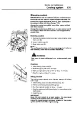
Страница 177: ...me safe against frost even after draining There may be pockets of water left AWARNING Take care of waste oil liquids in an environmentally safe way Flushing 1 After draining close cock B 2 Refill through A with clean tap water 3 Start up engine and run at low idle for about 10 minutes 4 Stop the engine and drain the water Filling coolant The cooling system capacity when changing is approx 27 5 lit...

Страница 178: ...or similar Installing 3 Coat the gasket with petroleum jelly 4 Fill the filter with coolant 5 Screw on the filter until the gasket just touches the sealing sur face Then tighten the filter a further 1 2 a turn 6 Open the valve A The handle should now be vertical After installing 7 Wipe around the filter head and the filter until dry 8 Start up and run the engine until warm 9 Stop the engine and ch...

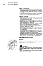
Страница 179: ...FF while the engine is running the alternator may be damaged Battery master switch A is located inside of the tool box which is located on the right side of the machine After finishing work for the day the battery master switch should be turned OFF Slow blow fuse These fuses are master fuses for the electrical systems A Battery master switch B 40 A 2 EA C 140A D 80 A 2 EA If the electrical system ...

Страница 180: ...mmediately flush with large amounts of clean water and consult a doctor Checking electrolyte level 1 Open the cover of the battery box on the right side of the ma chine 2 Loosen cap A The electrolyte level should stand approx 10 mm 0 4 in above the cell plates If the level is too low 1 Top up with distilled water 2 Operate the machine after topping up so that the water is mixed in with the battery...

Страница 181: ...tension it should be possible to depress the belt ap prox 15 mm 0 6 in If above 15 mm replace the belt with a new one Sensitivity of alternator installation The alternator A installation is sensitive to incorrect connection therefore always follow the installation instructions below Disconnection Battery and alternator cables must not be disconnected while the engine is running A fault may then ar...

Страница 182: ...ect the earth ground lead of the welding equipment as close to the welding point as possible Before welding remove all paint from an area of at least 10 cm 4 in around the point of welding Paint which is heated gives off unhealthy gases All paint decomposes when heated and forms a great number of compounds which may cause irritation and be dangerous to ones health after repeated or prolonged expos...

Страница 183: ... Capacity Appliance I circuit No Capacity Appliance I circuit Fl IOA IECU instrument electronic con trol unit F16 15A Stan switch F2 1OA Work lamp deck F17 5A Cab lamp F3 20A Work lamp boom F18 1OA Cassette radio F4 1OA Wiper washer F19 20A Auxiliary heater F5 F20 1OA Power outlet F6 1OA Cigar lighter F21 15A Fuel filler pump F7 bA Horn F22 F8 20A Air conditioner F23 F9 25A Work lamp rear counterw...

Страница 184: ...ty locking lever down to lock the system secure ly See Safety locking system on page 81 and stop the en gine 3 Turn the engine starting switch to ON cD position Do not start the engine 4 Turn the starting switch to OFF 0 position 5 Release internal pressure of the hydraulic tank through the air breather of the hydraulic tank 6 Open the right side of upper structure and check the oil level by sight...

Страница 185: ... 81 and stop the en gine 4 Release the internal pressure of the tank through air breather A 5 Unscrew cover B 6 Remove 0 ring C and strainer D 7 Place a container under the drain plug F 8 Remove the protecting cap for drain plug F and attach drain hose G which is the same hose as that used for draining en gine oil 9 Drain the oil 10 Disconnect the hose and install the protecting cap 11 After clean...

Страница 186: ...lter E 3 Clean the dismantled parts 4 Install a new filter and all parts When mounting cover A fasten the bolts while pressing down on the cover 5 Run the engine at low idle speed for 10 minutes to remove the air 6 Stop the engine Replacing cartridge for drain filter Replace the cartridge for the drain filter after the first 250 hours and then every 500 hours 1 Place a container under the drain fi...

Страница 187: ... strainer every 2000 hours or replace when neces sary 1 Press air breather A to release the internal pressure at the tank 2 Unscrew cover B and pull out strainer C 3 Clean or replace the strainer according to operating hours Replacing element in the air breather on hydraulic tank Replace the element in the air breather every 2000 hours or when necessary In dusty working environments the air breath...

Страница 188: ...ammer circuit ev ery 200 hours on the basis of hammer working hours 1 Stop the engine 2 Remove the filter case D by using a wrench 3 Remove the filter element C 4 Inspect 0 ring A and back up ring B for any damage 5 Replace damaged items 6 Install a new filter element 7 Install the filter case Tightening torque for the filter case D 4 5 kgf m S83205 ...

Страница 189: ...ive unit It is very important that the oil level is always correct and that it is checked at working temperature Therefore remember The swing drive unit may not drive correctly and thus be dam aged if there is too little oil Too much oil makes the oil foam which causes the swing drive unit to overheat AWARNING Immediately after operating the machine the oil is hot Allow the oil to cool ...

Страница 190: ...n drain valve C and drain the oil to adjust to the correct level Then close drain valve C Changing oil of swing drive unit Change the oil after the first 500 hours and then every 1000 hours 1 Find a container for receiving the drained oil 2 Place the container under the valve on the swing drive unit for receiving the drained oil 3 Remove protecting cap and connect drain hose which is the same hose...

Страница 191: ... always correct and that it is checked at working temperature Therefore remember The track drive unit may not drive correctly and thus be dam aged if there is too little oil Too much oil makes the oil foam which causes the track drive unit to overheat WARNING Immediately after operating the machine the oil is hot Allow the oil to cool Residual pressure in the drive unit may cause the plug to be di...

Страница 192: ...on page 211 Changing oil in track drive unit Change the oil initial 500 hours and every 2000 hours 1 Find a container above 7 liters for receiving the drained oil 2 Turn the case so that drain plug A is at the bottom 3 Put a container under drain plug A 4 Remove drain plug A oil level check plug B and drain the oil 5 Check the 0 ring on the plug if damaged change it 6 Install drain plug A 7 Remove...

Страница 193: ...ncy 1 Stop the engine by turning the ignition key to STOP 0 posi tion 2 Turn the ignition key to Running c1 position 3 Move the operating lever to boom down position to lower the attachment under its own weight Accumulator releasing pressure 1 Completely lower the attachment to the ground 2 Keep all the attachments such as hammer closed 3 After stopping the engine turn the starting switch to Runni...

Страница 194: ...hree times beginning with step 3 9 Apply grease to the swing bearing until grease can be seen es caping from the swing bearing seals 10 Take care not to supply excessive a mount of grease 11 After greasing clean off the superfluous grease completely Checking grease of swing bath 1 Park the machine on a level surface 2 Lower the bucket to the ground 3 Turn the starting key to STOP 0 position 4 Move...

Страница 195: ...gh the grease nipples using a hand or power grease gun After greasing clean off the superfluous grease Immediately after working under water grease the submerged parts such as the bucket pins to remove the old grease regardless of the grease interval Grease specification See Recommended lubricants on page 211 1 Boom cylinder mounting pin 2 points 7 Bucket cylinder mounting pin 1 point 2 Boom mount...

Страница 196: ...he ground as illustrated and stop the engine Refill the grease through the grease fittings using a hand or power grease gun After refilling grease clean off the overflow grease Immediately after working under water refill new grease to the submerged parts like the bucket pins to remove the old grease regardless of the grease refilling cycle time Grease specification See Recommended lubricants on p...

Страница 197: ...Retinax HDX2 I Alvania HDX2 Retinax EP2 Alvania EP2 TOTAL Multis MS2 Multis EP2 CASTROL Pyro LM Pyroplex Red Alternatives are not recommended when the ambient temperature is above 40 C Mixability of types of grease with different additives Mixability of types of grease with additives Lithium Calcium Lithium complex Calcium complex Aluminium complex Clay Lithium Calcium Lithium complex Calcium comp...

Страница 198: ...reduced Therefore clean it periodically Installing and dismantling the filter 1 Unscrew bolts A 2 Pull filter lever B for air conditioner ambient filter C push the latches E open the cover and take out the main filter D 3 Clean the filter with compressed air 4 If the filter is damaged or heavily contaminated replace it with a new one 5 Install the filter and assemble it in reverse order Adjusting ...

Страница 199: ...rly engaging each other causing interference and high loads Due to abrasive particles in the material it significant y ac celerates wear rates of the sprockets pins I bushings idlers and track links as the track load and tension increase Generally pack ing effects cannot be controlled except by constant cleaning Ire moval of the material Therefore thoroughly clean the undercarriage at least daily ...

Страница 200: ...track tension increasing slack AWARNING Valve A may suddenly dislodged due to the high pressure of the compressed grease in the cylinder When loosening valve A do not loosen it more than one turn Do not loosen other parts except valve A Step aside from the trajectory path of the valve If the tension can not be adjusted by the way shown in this manual contact an authorized Volvo CE dealer workshop ...

Страница 201: ... the track shoes are likely to be damaged Therefore check for looseness and tighten the bolts to specified torque 85 5 kgf m Retightening After tightening with a torque of 85 5 kgf m check whether the nut and the shoe are in full contact with the mating surfaces of the link Tightening order Tighten the bolts in the order as shown in the figure ...

Страница 202: ... and Put the safety locking lever down to lock the system securely See Safety locking system on page 81 S80293A WARNING Before removing the locking pins always wear eye protection Standard type transverse pin Korea 1 Drive out pin B using a hammer and punch being careful not to damage lock washer C Use a round bar with a smaller diameter than the pin as a Punch 2 Clean the surface of adapter D ins...

Страница 203: ...er fitting the tooth insert a new lock pin B into the pin hole and groove and lightly tap it into position 4 Check the following after changing the bucket tooth Check if the inserted locking pin is flush with the surface of the tooth If required slightly knock locking pin B inserted at one di rection upper face of the tooth direction to make it flush with Slightly knock the tip of the tooth upward...

Страница 204: ...en screws H and ADD or REMOVE shims to obtain the correct clearance Use the same quantity of split shims on each half 7 After the shim adjustment tighten screws H to specified torque 27 kgf m 195 lbf ft 8 Check clearance D adjust if required 9 Slide code rings G back into position NOTE Original shim quantity E is 12 6 x 2 NOTE Keep removed shims in the tool box as spares Adjust clear ance D each t...

Страница 205: ...earing IMPORTANT Wipe off grease nipples and the grease gun before greasing to avoid introducing sand and dirt particles with the grease Symbol key for Lubrication and service chart These standard symbols are used in the Lubrication and service chart see the adjacent table 2 3 7 8 9 iLi lOt lol 10 11 12 LJ F UI U I 1 13 14 15 i7 1 ilili S82040 19 1 Engine oil filling point 2 Grease lubrication poi...

Страница 206: ...Service and maintenance 204 Lubrication and service chart Lubrication and service chart 10 daily 50 250 500 1000 and 2000 hour ser vices ...

Страница 207: ...draulic oil level 182 Tightening of track shoe bolts 199 Measure page Daily every 50 hours Lubricate Grease to attachment 193 Measure page Every 100 hours After you have carried out Daily and 50 hour services Check Inspecting and adjusting track slack Clean if required 197 Sediment from fuel tank 166 Measure page Every 200 hours After you have carried out Daily 50 and 100 hour services Change Elem...

Страница 208: ...0 Grease to slewing gear bearing 192 Measure page Every 500 hours After you have carried out Daily 50 100 200 and 250 hour services Check Density of anti freeze 174 Grease of swing bath 192 Water pump fan belt tension 176 Change Engine oil and fiTter 163 165 CH 4 214 First change after 250 hours 165 Fuel filter 167 Water separator element 168 Hydraulic cartridge of drain filter 184 First change af...

Страница 209: ...Air cleaner primary filter 172 Coolant filter 176 Hydraulic oil return filter First change after 250 hours 184 Hydraulic element of pilot filter First change after 250 hours 185 Oil of swing drive unit First change after 500 hours 188 Measure page Every 1500 hours After you have carried out Daily 50 100 250 and 500 hour services Check Valve clearance adjusting 161 ...

Страница 210: ... filter 172 Coolant coolant filter not equipped machine 175 Hydraulic oil 183 Air breather element on hydraulic tank if required 185 Oil of track drive unit 190 First change after 500 hours Clean Suction strainer hydraulic tank 185 Measure page Every 3000 hours After you have carried out Daily 50 100 200 250 500 1000 and 1500 hour services Change Coolant 3000 hours if coolant filter is equipped 60...

Страница 211: ...al has passed they should be re paired or replaced immediately If the hose clamps show any deterioration such as deformation or cracking re place the clamps at the same as the hoses If the hose clamps show any deterioration such as deformation or cracking replace the clamps at the same as the hoses When replacing the hoses always replace the 0 rings gaskets and other such parts at the same time As...

Страница 212: ...Service and maintenance 210 Periodic replacement of safety critical parts ...

Страница 213: ...Pin and bushing Grease Multi purpose EP grease NLGI 2 lSOL XBCFB2 Fuel Diesel fuel ASTM D975 No 1 ASTM D975 No 2 Cooling system Coolant Use the same coolant as filled before see page 174 Air conditioner system Refrigerant HFC R134a C F I I I I 30 20 10 0 10 20 30 40 50 22 4 14 32 50 68 86 104 122 Installed at factory NOTE When starting the engine in an ambient temperature of lower than 0 C be sure...

Страница 214: ...25 C 13 F 40 35 C 31 F 50 46 C 51 F 60 The concentrated coolant must not be mixed with water that contains a high degree of lime hard water salt or metals The clean water for the cooling system must also meet the following requirements Description Value Total number of solid particles 340 ppm Total hardness 9 5 dH Chloride 40 ppm Sutphate 100 ppm pH value 5 5 9 Description Value Silica 20 mg SiO2 ...

Страница 215: ...e oil Changing coolant Hydraulic oil Oil of swing drive unit Oil of track drive unit Changing filter Engine oil filter Fuel filter Water separator element Air cleaner primary filter Air cleaner secondary filter Coolant filter Air conditioner heater filter Hours 500 CH 4 2000 1000 1st 500 2000 1st 500 Hours 500 CH 4 500 500 1000 2000 1000 1000 Page no 163 175 183 188 190 Page no 165 167 168 171 172...

Страница 216: ...r Battery Horn sound level at 7m Head light type Hydraulic system Main pump Model Type Volvo D6DEAE2 4 stroke 6 cylinder straight water cooled direct injection diesel engine turbocharger inter cooled 145 PSI 1900 rpm 66 kgfm 1425 rpm 98mm x 126mm 5 71 18 4 1 800 rpm 40 2000 rpm 40 153624 Forced circulation 200 500 kPa Intake 0 3 mm Exhaust 0 5 mm 25 MPa MVS 216 glkwhr 4 8 kW 12 V x 2 EA 95 5 dB Ha...

Страница 217: ...iston motor Rated pressure 350 kgf cm2 4980 psi Gear box Type 3 stage planetary Brake type Wet disc spring applied hydraulic release Swing motor and reduction gear Swing motor Model M2x 120 Type Fixed swash plate piston motor Rated pressure 270 kgf cm2 3840 psi Gear box Type Control pedals Model Stroke Operating force Control levers Model Stroke Operating force 2 stage planetary RCVD8C 12 4 degree...

Страница 218: ...eak application 0 3 0 2 0 6 Mining application 0 5 0 3 0 6 Transfer movement 0 3 0 2 0 8 The following vibration directions are defined X fore and aft Y lateral Z vertical The whole body vibration values given above have been taken from ISO CEN Technical Report XXXXXXX under development NOTE These whole body vibration emission values were determined at particular operating and terrain conditions a...

Страница 219: ...od 2331 7 8 2331 7 8 2331 7 8 E Counterweight clearance 1025 3 4 1025 3 4 1025 3 4 G Tumbler length 3660 12 0 3660 12 0 3660 12 0 H Track length 4460 14 8 4460 14 8 4460 14 8 I Track gauge 2390 710 2390 710 2390 710 J Shoe width mm 600 600 600 J Shoe width North America mm ft in 800 2 7 800 2 7 800 2 7 500 1 7 500 1 7 500 1 7 K Minimum ground clearance 460 1 6 460 1 6 460 1 6 L Overall length 9650...

Страница 220: ...7 8 2331 7 8 F Counterweight clearance ftin 1025 3 4 1025 3 4fl 1025 3 4fl 1025 3 4fl 3370 3370 3370 3660 0 Tumbler length 11 1 111 11 1 12 0 4170 4170 4170 4460 H Track length 13 8 13 8 13 8 14 8 2040 2040 2040 2390 I Track gauge 6 8 6 8 6 8 710 J Shoe width mm 500 500 500 800 500 500 500 J Shoe width North America 1 8 1 8 1 8 460 460 460 460 K Min ground clearance 1 6 1 6 16 1 6 mm 9650 9590 957...

Страница 221: ... 1800 kg rn3 C Applicable for general purpose up to 1500 kg rn3 D Applicable for general purpose up to 1200 kg rn3 E Not available Volvo bucket and LC undercarriage Description Direct fit GP bucket Quick fit GP bucket Bucket capacity SAE CECE 9501 1 24 yd3 8601 1100 1 44 yd3 9901 12501 1 64 yd3 1120 9501 1 24 yd3 860 11001 1 44 yd3 9901 Cutting width 1050 mm 1180 mm 1310 mm 1050 mm 1180mm Weight 7...

Страница 222: ... 81601b 1100 1050 1025 900 3030 IbIyd3 1 44 1 37 1 34 1 18 RBbucket2 Ot m3 1025 975 950 825 3370 Ib yd3 1 34 1 28 1 24 1 08 Maximum permitted buckets for quick fit standard counterweight Undercarriage Unit LC Monobloc Boom 5 7 m Boom 18 8 Dipper Arm 2 5 m Arm 8 2 2 9 m Arm 9 6 2 9 m HD Arm 9 6 3 9 m Arm 12 10 GPbucketl 5t1m3 1375 1275 1250 1100 2530 lb yd3 1 80 1 67 1 64 1 44 GPbucketl 8t m3 1200 ...

Страница 223: ...60 lb 1200 1125 1100 950 3030 lb yd3 1 57 1 47 1 44 1 24 RBbucket2 0tlm3 1100 1025 1000 900 3370 lb yd3 1 44 1 34 1 31 1 18 Maximum permitted buckets for quick fit option counterweight Undercarriage Unit LC Monobloc Boom 5 7 m Boom 18 8 Dipper Arm 2 5 m Arm 8 2 2 9 m Arm 9 6 2 9 m HD Arm 9 6 3 9 m Arm 12 10 GPbucket 1St rn3 1475 1375 1350 1175 2530 lb yd3 1 93 1 80 1 77 1 54 GPbucketl 8t m3 1300 1...

Страница 224: ...t 1 8 tlm3 1075 1000 975 850 3030 lb yd3 1 41 1 31 1 28 1 11 RBbucket2 otlm3 1000 925 900 800 3370 lb yd3 1 31 1 21 1 18 1 05 Maximum permitted buckets for quick fit Undercarriage Unit NLC Monobloc Boom 5 7 m Boom 18 8 Dipper Arm 2 5 m Arm 2 9 m Arm 2 9 m HD Arm 3 9 m Arm 82 9 6 96 1210 GPbucketl 5t m3 1325 1225 1200 1050 2530 lb yd3 1 73 1 60 1 57 1 37 GP bucket 1 8 tIm3 1150 1075 1050 925 3030 l...

Страница 225: ...5 2 5 2 670 670 670 Width 2 2 2 2 2 2 kg 1785 1890 2090 Weight lb 3940 4170 4610 Includes cylinder piping and pin Arm Description mm ft in 2 5 m 8 2 2 9 m 9 6 2 9 m 9 6 3 9 m 12 10 Length 3530 11 7 3900 1210 3900 12 10 4940 16 2 Height 880 211 880 2 11 880 211 820 2 8 Width 440 1 5 440 15 440 15 440 15 Weight kg lb 975 2150 1000 2210 1085 2390 1135 2500 Includes cylinder pin and linkage ...

Страница 226: ... SAE kN kg lb 130 4 13300 29330 130 4 13300 29330 130 4 13300 29330 Normal ISO kN kg 136 3 13900 136 3 13900 136 3 13900 Power boost ISO kN kg 147 1 15000 147 1 15000 147 1 15000 Tearout force Normal SAE kN kg lb 110 4 11260 24830 95 6 9750 21500 80 2 8180 18040 Power boost SAE kN kg lb 117 2 11950 26350 103 0 10500 23150 86 3 8800 19400 Normal ISO kN kg 113 7 11600 25580 98 2 10010 22070 81 9 835...

Страница 227: ...Power boost SAE kN kg lb 130 4 13300 29330 130 4 13300 29330 130 4 13300 29330 Normal ISO kN kg 136 3 13900 136 3 13900 136 3 13900 77 8 7930 Power boost ISO kN kg 147 1 15000 147 1 15000 147 1 15000 Tearout force Normal SAE kN kg lb 110 4 11260 24830 95 6 9750 21500 80 2 8180 18040 44 1 4500 9920 Power boost SAE kN kg lb 117 2 11950 26350 103 0 10500 23150 86 3 8800 19400 Normal ISO kN kg 113 7 1...

Страница 228: ...0 35 4 B Maximum digging reach on ground 9350 30 8 9750 31 12 10610 3410 C Maximum digging depth 6330 20 9 6730 221 7730 25 4 D Maximum cutting height 9220 30 3 9450 31 0 9620 31 7 E Maximum dumping height 6430 21 1 6650 21 10 6850 22 6 F Maximum vertical wall digging depth 5520 18 1 5830 19 2 6570 21 7 a Minimum front swing radius 3670 12 0 3650 1112 3640 1111 H Maximum digging depth 8 level 6110...

Страница 229: ... reach on ground 9280 30 5 9680 31 9 10530 347 15710 51 7 C Maximum digging depth 5930 195 6300 208 7240 23 9 12100 398 D Maximum cutting height 10390 341 10710 35 2 11180 36 8 13300 438 E Maximum dumping height 7470 24 6 7780 25 6 8270 27 2 10950 3511 F Maximum vertical wall digging depth 4910 16 1 5320 17 5 6180 20 3 G Minimum front swing radius 2740 8 12 2440 8 0 2840 9 4 H Maximum digging dept...

Страница 230: ...Specifications 228 Care and maintenance journal Care and maintenance journal Date Hours Signature Notes ...

Страница 231: ...Specifications Care and maintenance journal 229 Date Hours Signature Notes ...

Страница 232: ...Specifications 230 Care and maintenance journal Date Hours Signature Notes ...

Страница 233: ...Specifications Care and maintenance journal 231 Date Hours Signature Notes ...

Страница 234: ...Specifications 232 Care and maintenance journal Date Hours Signature Notes ...

Страница 235: ...Specifications Care and maintenance journal 233 Date Hours Signature Notes ...

Страница 236: ...Specifications 234 Care and maintenance journal Date Hours Signature Notes ...

Страница 237: ...Specifications Care and maintenance journal 235 Date Hours Signature Notes ...

Страница 238: ...Specifications 236 Care and maintenance journal Date Hours Signature Notes ...

Страница 239: ...Specifications Care and maintenance journal 237 Date Hours Signature Notes ...

Страница 240: ...Specifications 238 Care and maintenance journal Date Hours Signature Notes ...

Страница 241: ...s warning and control lamps 120 Checking oil level in track drive unit 190 Checking oil level of swing drive unit 188 Checks oil changes and lubrication 205 Cleaning primary filter 172 Cleaning radiator oil cooler and condenser fins 173 Cleaning suction strainer 185 Closing the upper window 82 Coat hook 84 Communication equipment installation 3 Contents 5 Controls 73 Coolant 174 Coolant 212 Coolin...

Страница 242: ...ator duties 95 Operator manual storage 85 Operator qualifications 95 Operator seat 79 Optional parts 140 Parking 127 Periodic replacement of safety critical parts 209 Permissible depth of water 98 Plates and decals 12 Presentation 7 Preventive maintenance 43 Primary filter B 171 Procedures before starting 118 Procedures in cold weather 122 Product plates 12 Protection from electromagnetic interfer...

Страница 243: ...r heavy objects 128 Towing method 128 Track drive unit 189 Track motor and gearbox 8 Track slack 197 Track slack adjusting 198 Transporting the machine 100 Travel direction control 124 Turbocharger 170 Use handholds and steps for climbing on off 161 Valve clearance 165 Vibration and sound information 216 Volvo bucket and LC undercarriage 219 Volvo bucket and LC undercarriage 219 Warranty inspectio...

Страница 244: ...Ref No VOE 21B1001632 English Printed in Korea CST Volvo Pyongtaek ...

Отзывы:

Похожие инструкции для EC210B