48
Repair Instructions
7
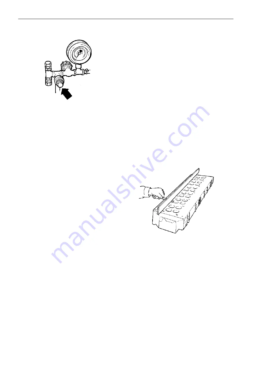
Screw in the relief valve knob so that a pressure of
50 kPa (0.5 kp/cm
2
) is obtained on the pressure
gauge. Hold the pressure for 1 minute.
8
Then raise the pressure to 150 kPa (1.5 kp/cm
2
).
Lock the relief valve knob with the lock ring and close
the cock.
Check after one or two minutes if the pressure is
sinking or if there are air bubbles in the water bath.
Any leakage at the copper injector sleeves is rem-
edied according to “Replacing copper injector
sleeves” on pages 52 and 53.
Cylinder head, inspection
Cracks
When checking before reconditioning heat cracks can
sometimes be seen between the valve seat and in-
jector nozzle in engines that have a large number of
operating hours.
The cylinder head does not require changing because
of heat cracking
The crack begins at the copper injector sleeve and
goes towards the valve seat position. The cause of
the crack may be that the injector mounting nuts are
too tight, incorrectly torqued. Cracks of this type
have never been the cause of gas or fluid leakage,
because the crack has not continued through to the
bottom of the cylinder head.
When leakage is observed it has been because of
pollutants or damage to the copper sleeve seats.
See instruction “Cleaning the copper sleeve seat.”
Distortion
The check is carried out with a feeler gauge and
straight edge ruler, the edge of which is ground to a
tolerance according to DIN 874/Normal.
The measurement is carried out first lengthways and
then diagonally. If distortion exceeds 0.10 mm in 100
mm length or 0.20 in the entire length, the cylinder
head should be replaced.
NOTE! The cylinder block cannot be ground flat.
If leakage is observed or if the blown marks the
measurement is not necessary because a cylinder
head in this condition must be replaced.
Содержание 300 Series
Страница 1: ...Engine Body Workshop Manual 2 0 B 31 32 41 42 43 44 300 series ...
Страница 2: ......
Страница 94: ...92 References to Service Bulletins Group No Date Regarding ...
Страница 96: ...7741725 1 English 10 2001 ...


