background image

29

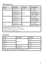
Wechselspannung

Bereich

Genauigkeit

Auflösung

Frequenybereich

600 mV

±(1,0% + 10)

0,1 mV

40 – 100 Hz

6 V

±(1,0% + 10)

0,001 V

40 – 1,000 Hz

±(2,8 % + 8)

1,000 – 10,000 Hz

±(5,0 % + 15)

10,000 – 50,000 Hz

60 V

±(2,5% + 10 )

0,01 V

40 – 1,000 Hz

±(2,8 % + 8)

1,000 – 10,000 Hz

±(5,0 % + 15)

10,000 – 50,000 Hz

600 V

±(1,0% + 10)

0,1 V

40 – 1,000 Hz

±(6,0 % + 10)

1,000 – 10,000 Hz

Überlastschutz 600 V; Impedanz: ca. 10 MΩ
TrueRMS im Messbereich von 10 – 95%: Scheitelfaktor 
(Crest Factor): max. 3,0 (bei 600 max. 1,5)

Gleichstrom

Bereich

Genauigkeit

Auflösung

600 µA

±(0,7 % + 5)

0,1 µA

6000 µA

1 µA

60 mA

0,01 mA

600 mA

±(1,0 % + 8)

0,1 mA

10 A

±(1,8 % + 3)

0,01 A

Überlastschutz: Sicherungen 600 V;  500 mA (µAmA) / 10 A(10 A)

Содержание VC611BT

Страница 1: ...VC611BT DIGITAL MULTIMETER BEDIENUNGSANLEITUNG Seite 4 32 VC611BT DIGITAL MULTIMETER OPERATING INSTRUCTIONS Page 33 59 Version 11 13 ...

Страница 2: ...te finden Sie in dem Inhaltsverzeichnis mit Angabe der entsprechenden Seitenzahlen auf Seite 4 These Operating Instructions accompany this product They contain important information on setting up and using the device You should refer to these instructions even if you are buying this product for someone else Please retain these Operating Instructions for future use A list of the contents can be fou...

Страница 3: ...3 1 2 3 4 5 6 7 8 9 10 11 12 13 Auto Power OFF Cancel 6000 Counts True RMS Multimeter CAT II 600V 600m Ama x 14 15 16 ...

Страница 4: ...ersicht 13 8 Displayangaben und Symbole 13 9 Gerät Einschalten 14 10 Messleitungen 15 11 Messung starten 15 12 RANGE Funktion Manuelle Messbereichswahl 21 13 Hold Funktion 22 14 Max min Funktion 22 15 Auto Power Off Funktion 23 16 Displaybeleuchtung 23 17 Stativ 23 18 Wartung und Reinigung 24 19 Behebung von Störungen 26 20 Entsorgung 27 21 Technische Daten 28 ...

Страница 5: ...tät unserer Voltcraft Produkte bieten wir Ihnen mit einem fast unschlagbar günstigen Preis Leistungsverhältnis an Darum schaffen wir die Basis für eine lange gute und auch erfolgreiche Zusammenarbeit Wir wünschen Ihnen nun viel Spaß mit Ihrem neuen Voltcraft Produkt Alle enthaltenen Firmennamen und Produktbezeichnungen sind Warenzeichen der jeweiligen Inhaber Alle Rechte vorbehalten Bei technische...

Страница 6: ...herungen gegen Überlast abgesichert Die Spannung im Strom Messkreis darf 600 V in CAT ll nicht überschreiten Das Multimeter wird mit sechs 1 5 Volt Batterien des Typs C oder einer Spannung von 230 V AC 50 Hz betrieben Um Strom zu sparen wird das Gerät automatisch ausgeschaltet wenn es für einen Zeitraum von etwa 10 Minuten nicht benutzt wird Diese Funktion wird aktiviert wenn das Multimeter mit Ba...

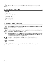
Страница 7: ...gen 1 Satz Krokoklemmen K Typ Temperaturfühler Bedienungsanleitung 4 ZEICHENERKLÄRUNG Ein Ausrufungszeichen in einem Dreieck zeigt wichtige Anweisungen in dieser Anleitung die unbedingt befolgt werden müssen Ein Blitzsymbol im Dreieck warnt vor einem elektrischen Schlag oder der Beeinträchtigung der elektrischen Sicherheit des Geräts CAT II Überspannungskategorie II für Messungen an elektrischen u...

Страница 8: ...währleistet wenn das Produkt sichtbare Schäden aufweist nicht mehr ordnungsgemäß funktioniert über einen längeren Zeitraum unter ungünstigen Umgebungsbedingungen gelagert wurde oder erheblichen Transportbelastungen ausgesetzt wurde Gehen Sie vorsichtig mit dem Produkt um Durch Stöße Schläge oder dem Fall aus bereits geringer Höhe wird es beschädigt Beachten Sie auch die Sicherheitshinweise und Bed...

Страница 9: ...rdnungsgemäße Netzsteckdose 230 V AC 50Hz des öffentlichen Versorgungsnetzes Ziehen Sie das Steckernetzteil nicht am Kabel aus der Netzsteckdose Die Netzsteckdose muss sich in der Nähe des Geräts befinden und leicht zugänglich sein Ziehen Sie bei längerer Nichtbenutzung den Netzstecker aus der Netzsteckdose Sollte die Netzleitung Beschädigungen aufweisen so berühren Sie sie nicht Schalten Sie zuer...

Страница 10: ...ende Isolierung beschädigt eingerissen abgerissen usw ist Um einen elektrischen Schlag zu vermeiden achten Sie darauf dass Sie die zu messenden Anschlüsse Messpunkte während der Messung nicht auch nicht indirekt berühren Über die fühlbaren Griffbereichsmarkierungen an den Messspitzen darf während des Messens nicht gegriffen werden Verwenden Sie das Multimeter nicht kurz vor während oder kurz nach ...

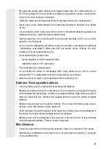
Страница 11: ...ten und neuen Batterien im Gerät kann zumAuslaufen der Batterien und zur Beschädigung des Geräts führen Nehmen Sie keine Akkus auseinander schließen Sie sie nicht kurz und werfen Sie sie nicht ins Feuer Versuchen Sie niemals nicht aufladbare Batterien aufzuladen Es besteht Explosionsgefahr Sonstiges Wenden Sie sich an eine Fachkraft wenn Sie Zweifel über die Arbeitsweise die Sicherheit oder den An...

Страница 12: ...ugspotenzial Minus 12 Messbuchse mAµAºCºF 13 Messbuchse 10 A 14 BAT AC Wahlschalter Gleichspannung Wechselspannung 15 Ein Ausschalter 16 Netzanschluss C14 Standardanschluss Drehschalter zur Auswahl der Messfunktion V Gleichspannung Wechselspannung in der Einheit Volt messen Ω Widerstand messen Piepton ein aus Diode Kapazität messen Hz Frequenz ºC Temperatur in der Einheit ºC messen ºF Temperatur i...

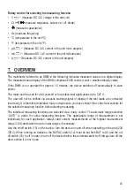
Страница 13: ...bereich eingestellt Beginnen Sie bei der Strommessung immer mit dem größten Messbereich 10 A und schalten Sie bei Bedarf auf einen kleineren Messbereich um Der Ein Ausschalter 15 auf der Rückseite dient zum Ein und Ausschalten des Geräts bei Netzbetrieb 230 V DC Bei Batteriebetrieb muss der Schalter BAT AC 14 von BAT auf AC gestellt werden um das Gerät vor dem Ende der automatischen Abschaltung au...

Страница 14: ...rsorgung bevor Sie das Stromversorgungsfach öffnen Trennen Sie die Messleitungen vom Gerät bevor Sie das Stromversorgungsfach öffnen Betreiben Sie das Messgerät auf keinen Fall im geöffneten Zustand Sie müssen eine neue vollständig geladene Batterie einlegen wenn Sie das Gerät zum ersten Mal in Betrieb nehmen oder wenn das Symbol für den Batteriewechsel angezeigt wird 1 Schieben Sie den BAT AC Wah...

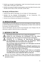
Страница 15: ... klemmen Sie diese an die Messpunkte 11 MESSUNG STARTEN Überschreiten Sie auf keinen Fall die max zulässigen Eingangsgrößen Berühren Sie keine Schaltungen oder Schaltungsteile wenn darin höhere Spannungen als 25 V ACrms oder 35 V DC anliegen können Lebensgefahr Kontrollieren Sie vor Messbeginn die angeschlossenen Messleitungen auf Beschädigungen wie z B Schnitte Risse oder Quetschungen Defekte Mes...

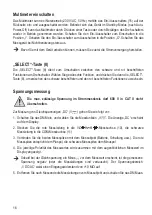
Страница 16: ... schwarz beschrifteten und den rot beschrifteten Funktionen zu wechseln Spannungsmessung Die max zulässige Spannung im Strommesskreis darf 600 V in CAT II nicht überschreiten Zur Messung von Gleichspannungen DC V gehen Sie wie folgt vor 1 Schalten Sie das DMM ein und wählen Sie die Messfunktion V Die Anzeige DC erscheint auf dem Display 2 Stecken Sie die rote Messleitung in die VΩ Hz Messbuchse 10...

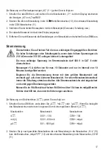
Страница 17: ...T II nicht überschreiten Messungen 5 A dürfen nur für max 10 Sekunden und nur im Intervall von 10 Minuten durchgeführt werden Beginnen Sie die Strommessung immer mit dem größten Messbereich und wechseln ggf auf einen kleineren Messbereich Vor einem Messbereichswechsel immer die Schaltung stromlos schalten Alle Strommessbereiche sind abgesichert und somit gegen Überlastung geschützt Messen Sie im 1...

Страница 18: ...sen A 0 001 10 A COM 10A mA 0 001 600 mA COM mAµA µA 0 01 6000 µA COM mAµA 2 Stecken Sie je nach gewählter Messfunktion die rote Messleitung in die Messbuchse 10 A 13 bzw die Messbuchse mAµAºCºF 12 und die schwarze Messleitung in die Messbuchse COM 11 3 Verbinden Sie die beiden Messspitzen in Reihe mit dem Messobjekt Generator Schaltung usw die augenblicklichen Messwert im Display angezeigt 4 Entf...

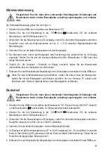
Страница 19: ...ssobjekt und schalten Sie das DMM aus Wenn Sie eine Widerstandsmessung durchführen achten Sie darauf dass die Messpunkte welche Sie mit den Messspitzen zum Messen berühren frei von Schmutz Öl Lötlack oder ähnlichem sind Solche Umstände können das Messergebnis verfälschen Diodentest Vergewissern Sie sich dass alle zu messenden Schaltungsteile Schaltungen und Bauelemente sowie andere Messobjekte unb...

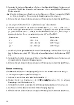
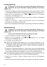
Страница 20: ...hten Sie bei Elektrolyt Kondensatoren unbedingt die Polarität 1 Schalten Sie das DMM ein und wählen den Messbereich 2 Stecken Sie die rote Messleitung in dieVΩ Hz Messbuchse 10 die schwarze Messleitung in die COM Messbuchse 11 3 In der Anzeige erscheint die Einheit nF Aufgrund des empfindlichen Messeingangs kann es bei offenen Messleitungen zu einer Wertanzeige im Display kommen Durch Drücken der ...

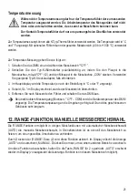
Страница 21: ...lich 3 Im Hauptdisplay wird die Temperatur je nach der Einstellung in C oder F angezeigt 4 Sobald OL im Display erscheint wurde der Messbereich überschritten 5 Entfernen Sie nach Messende den Fühler und schalten Sie das DMM aus Bei überbrücktem Messeingang Buchsen C ºF COM wird die Gerätetemperatur des DMM angezeigt Die Temperaturanpassung an die Umgebung erfolgt auf Grund des geschlossenen Gehäus...

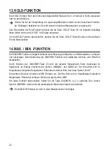
Страница 22: ...glicht während einer Messung die Maximal und Minimalwerte zu erfassen und anzuzeigen Nach Aktivierung der MAX MIN Funktion wird wahlweise der Max oder Min Wert festgehalten Durch Drücken der MAX MIN Taste 3 wird der aktuelle Messbereich fixiert Autorange ist deaktiviert Im Display erscheint das Symbol MINMAX und MANUAL Der Max Wert wird im Hauptdisplay fortlaufend festgehalten Erkennbar ist dieser...

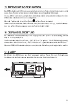
Страница 23: ...m Display angezeigt wenn die Funktion deaktiviert ist 16 DISPLAYBELEUCHTUNG Bei schlechten Lichtverhältnissen kann das Display beleuchtet werden Die Beleuchtung schaltet nach ca 10 s automatisch ab Zum Einschalten halten Sie die Taste LIGHT 8 für ca 2 s gedrückt Um die Beleuchtung vorzeitig abzuschalten halten Sie die Taste LIGHT erneut für ca 2 s gedrückt oder schalten das DMM aus Wenn das DMM mi...

Страница 24: ...ittel Benzine Alkohole oder ähnliches Dadurch wird die Oberfläche des Messgerätes angegriffen Außerdem sind die Dämpfe gesundheitsschädlich und explosiv Verwenden Sie zur Reinigung auch keine scharfkantigen Werkzeuge Schraubendreher oder Metallbürsten o a Zur Reinigung des Gerätes bzw des Displays und der Messleitungen nehmen Sie ein sauberes fusselfreies antistatisches und leicht feuchtes Reinigu...

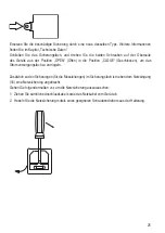
Страница 25: ...tion OPEN Offen in die Position CLOSE Geschlossen um das Stromversorgungsfach zu verriegeln Zusätzlich zu den Sicherungen für die Messleitungen im Sicherungsfach ist neben dem Netzeingang 16 eine Netzsicherung angebracht Gehen Sie folgendermaßen vor um die Netzsicherung auszutauschen 1 Ziehen Sie sämtliche Anschlusskabel sowie das Netzkabel vom Gerät ab 2 Hebeln Sie die Netzsicherung mittels eines...

Страница 26: ...emäß angeschlossen Kontrollieren Sie den Zustand Batteriewechsel Überprüfen Sie das Netzkabel Keine Messwertänderung Ist eine falsche Messfunktion aktiv AC DC Kontrollieren Sie die Anzeige AC DC und schalten die Funktion ggf um Stecken die Messleitungen zuverlässig in den Messbuchsen Kontrollieren Sie den Sitz der Messleitungen Ist die Sicherung defekt Kontrollieren Sie die Sicherungen Ist die Hol...

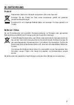
Страница 27: ...über den Hausmüll ist untersagt Schadstoffhaltige Batterien Akkus sind mit dem nebenstehenden Symbol gekennzeichnet das auf das Verbot der Entsorgung über den Hausmüll hinweist Die Bezeichnungen für das ausschlaggebende Schwermetall sind Cd Cadmium Hg Quecksilber Pb Blei die Bezeichnung steht auf den Batterien Akkus z B unter dem links abgebildeten Mülltonnen Symbol Ihre verbrauchten Batterien Akk...

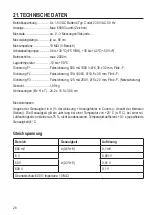
Страница 28: ... 10A 1000V Ø 10 5 x 38 mm Flink F Sicherung F3 Feinsicherung 125 mA 250 V Ø 5 x 20 mm Flink F Netzsicherung Gewicht 1 99 kg Abmessungen B x H x T 24 2 x 10 5 x 30 5 cm Messtoleranzen Angabe der Genauigkeit in der Ablesung Anzeigefehler in Counts Anzahl der kleinsten Stellen Die Genauigkeit gilt ein Jahr lang bei einer Temperatur von 23 C 5 C bei einer rel Luftfeuchtigkeit von kleiner als 75 nicht ...

Страница 29: ...2 8 8 1 000 10 000 Hz 5 0 15 10 000 50 000 Hz 600 V 1 0 10 0 1 V 40 1 000 Hz 6 0 10 1 000 10 000 Hz Überlastschutz 600 V Impedanz ca 10 MΩ TrueRMS im Messbereich von 10 95 Scheitelfaktor Crest Factor max 3 0 bei 600 max 1 5 Gleichstrom Bereich Genauigkeit Auflösung 600 µA 0 7 5 0 1 μA 6000 μA 1 μA 60 mA 0 01 mA 600 mA 1 0 8 0 1 mA 10 A 1 8 3 0 01 A Überlastschutz Sicherungen 600 V 500 mA µAmA 10 A...

Страница 30: ...0 0 01 mA 40 10 000 Hz 4 5 10 000 15 000 Hz 600 mA 2 10 0 1 mA 40 10 000 Hz 5 15 10 000 15 000 Hz 10 A 3 10 0 01 A 40 1 000 Hz 3 15 1 000 5 000 Hz Überlastschutz Sicherungen 600 V TrueRMS im Messbereich von 10 100 Widerstand Bereich Genauigkeit Auflösung 600 Ω 0 8 3 0 1 Ω 6 kΩ 0 8 5 0 001 kΩ 60 kΩ 0 01kΩ 600 kΩ 0 1kΩ 6 MΩ 1 2 5 0 001MΩ 60 MΩ 1 8 15 0 01MΩ Überlastschutz 600 V ...

Страница 31: ... nF 60 nF 0 01 nF 600 nF 0 1 nF 6 μF 0 001 μF 60 μF 0 01 μF 600 μF 5 8 0 1 µF 6 mF 8 10 0 001 mF Überlastschutz 600 V Frequenz Bereich Genauigkeit Auflösung 6 kHz 0 1 10 1 Hz 60 kHz 0 01 kHz 600 kHz 0 1 kHz 6 MHz 0 001 MHz 60 MHz 0 01 MHz Überlastschutz 600 V ...

Страница 32: ...0 to 400 ºC 2 5 8 400 to 1000 ºC 3 5 40 to 32 ºF 12 10 1 ºF 32 to 752 ºF 2 5 10 752 to 1832 ºF 3 5 8 Diodentest Prüfspannung Auflösung ca 2 70 V 0 001 V Überlastschutz 600 V Akust Durchgangsprüfer Prüfspannung Auflösung ca 1 2 V 1 Ω Überlastschutz 600 V 10 Ω Dauerton ...

Страница 33: ...1 8 Display indication and symbols 42 9 Power the product 42 10 Measuring lines 43 11 Starting the measurement 44 12 Range function manual measurement range selection 50 13 Hold function 50 14 Max min function 51 15 Auto power off function 51 16 Display illumination 51 17 Stand 52 18 Maintenance and cleaning 52 19 Troubleshooting 54 20 Disposal 54 21 Technical data 55 ...

Страница 34: ...amily provide the optimum solution even for the most demanding tasks And the remarkable feature is we offer you the mature technology and reliable quality of our Voltcraft products at an almost unbeatable price performance ratio In this way we aim to establish a long fruitful and successful co operation with our customers We wish you a great deal of enjoyment with your new Voltcraft product All na...

Страница 35: ...00 V in CAT II The multimeter runs on six 1 5 V C batteries or at a voltage of 230 V AC 50 Hz To save electricity the device turns off automatically after about 10 minutes of disuse This function is activated when running the multimeter on batteries or at 230 V AC When operating at over 230 V AC you can turn off the multimeter manually using the on off switch 15 on the back When running on batteri...

Страница 36: ...be observed The triangle containing a lightning symbol warns of danger of an electric shock or of the impairment of the electrical safety of the device CAT II Overvoltage category II for measurements on electric and electronic devices connected to the mains supply with a mains plug This category also covers all lower categories e g CAT I for measuring signal and control voltages This device is CE ...

Страница 37: ...nt conditions or has been subjected to any serious transport related stresses Please handle the product carefully Jolts impacts or a fall even from a low height can damage the product Also observe the safety and operating instructions of any other devices which are connected to the product Products operated using the mains voltage must be kept out of the reach of children For this reason be partic...

Страница 38: ...d then carefully pull the mains plug from the mains socket Never use the product if the mains cable is damaged A damaged mains cable may only be replaced by the manufacturer a workshop commissioned by the manufacturer or a similarly qualified person so as to prevent any danger Never plug in or unplug the mains plug when your hands are wet Do not pull the mains adapter out of the wall outlet by its...

Страница 39: ...h the meter on immediately after it was taken from a cold to a warm environment The condensation that forms might destroy your device Allow the device to reach room temperature before switching it on Batteries Rechargeable batteries Correct polarity must be observed while inserting the batteries Batteries should be removed from the device if it is not used for a long period of time to avoid damage...

Страница 40: ...t range switching 3 MAX MIN button maximum minimum display switching 4 Cancel Auto power OFF button Turning the auto power off function on off 5 LIGHT button light button 6 Rotary control for selecting the measuring function 7 Adjustable stand 8 SELECT button 9 Hold button hold button 10 VΩ Hz measuring jack with commensurability Plus 11 COM measuring jack reference potential Minus 12 mAµAºCºF mea...

Страница 41: ...plications up to CAT II The user will not be notified via acoustic warning signal or display if the test leads are connected incorrectly It is therefore imperative that you make sure you have chosen the correct test sockets for the selected measuring function before starting measuring The individual measuring functions are selected via a rotary control The automatic range selection AUTO is active ...

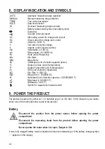
Страница 42: ... ºC Degree Celsius unit of temperature ºF Degree Fahrenheit unit of temperature Ω Ohm unit of electric impedance kΩ Kilo Ohm 1000 Ω MΩ Mega Ohm 1000000 Ω nF Nanofarad unit of electric capacity 0 000000001 F µF Microfarad 0 000001 F mF Millifarad 0 001 F Symbol for capacitance measurement 9 POWER THE PRODUCT The product is powered by either six 1 5 V batteries type C or 230 V AC 50 Hz Based on your...

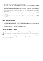
Страница 43: ...e and lock the power compartment by turning the two screws inside from the position OPEN to CLOSE Alternating current power 1 Slide the BAT AC selection switch 14 to the position AC 2 Connect the power cord standard C13 to the power inlet standard C14 16 at the back of the multimeter 3 Connect the power plug of the power cord to a mains outlet 10 MEASURING LINES A pair of measurement leads and a p...

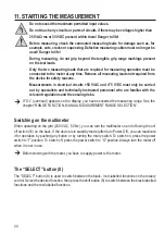
Страница 44: ...tructed personnel who are familiar with the relevant regulations and the ensuing risks If OL overload appears on the display you have exceeded the measuring range See the chapter RANGE FUNCTION MANUAL MEASUREMENT RANGE SELECTION Switching on the multimeter When operating on the grid 230 V AC 50 Hz you can turn the multimeter on and off using the on off switch 15 on the back If the device is in sta...

Страница 45: ...sured value If a minus appears in front of the measured value for direct voltage the measured voltage is negative or the measuring leads are swapped The voltage range V DC AC shows an input impedance of 10 MΩ 5 After measuring remove the measuring leads from the measured object and turn off the DMM Proceed as follows to measure alternating voltages AC V 1 Switch on the DMM and select measuring fun...

Страница 46: ...μA range otherwise the fuses trigger Proceed as follows to measure direct current DC A 1 Switch on the DMM and select A mA or µA If you are not sure about the measured range start with a larger range A Measuring function Measuring range Measuring jacks A 0 001 10 A COM 10A mA 0 001 600 mA COM mAµA µA 0 01 6000 µA COM mAµA 2 Depending on the measuring function chosen plug the red measuring lead int...

Страница 47: ...test prods in series with the object to be measured generator circuit etc the display indicates the polarity of the measured value together with the currently measured value 4 After measuring remove the measuring leads from the measured object and turn off the DMM Frequency measuring The DMM can be used to measure and indicate signal voltage frequencies from 0 001 Hz to 60 MHz Proceed as follows t...

Страница 48: ... measuring remove the measuring leads from the measured object and turn off the DMM If you carry out a impedance measurement make sure that the measuring points you touch with the test probes are free from dirt oil solderable lacquer or similar Such circumstances can falsify the measured result Diode test Make sure that all the circuit parts switches and components and other objects of measurement...

Страница 49: ... the voltage and discharged Always observe polarity with electrolyte capacitors 1 Switch on the DMM and select measuring range 2 Plug the red measuring lead into the VΩ Hz measuring jack 10 and the black measuring lead into the COM measuring socket 11 3 The display shows the unit nF Due to the sensitive measuring input the display may show a value if the measuring leads are open By pressing the bu...

Страница 50: ...easuring remove the sensor and turn off the DMM When the measuring input is bridged sockets C ºF COM the DMM device temperature is indicated Due to the closed casing the temperature is only slowly adapted to the ambience temperature 12 RANGE FUNCTION MANUAL MEASUREMENT RANGE SELECTION The RANGE function enables manual measuring range selection in some measurement with an automatic measuring range ...

Страница 51: ...is activated The MAX MIN function is not available for all measuring functions 15 AUTO POWER OFF FUNCTION The DMM turns off automatically after 10 minutes if no button or rotary control is operated This function protects the battery saves battery power and extends the operating time To reactivate the DMM after automatic shutdown use the rotary control or press any button The symbol will show on th...

Страница 52: ...re cleaning the device Live components may be exposed if covers are opened or parts are removed unless this can be done without tools The connected lines must be disconnected from the meter and all measuring objects before the device is cleaned or repaired Switch off the DMM Do not use any carbon containing cleaning agents or petrol alcohol or the like to clean the product They will damage the sur...

Страница 53: ... Remove the Phillips screw from the lid of the fuse compartment Remove the lid Replace the broken fuse with a new one of the same type See the chapter technical data Close the fuse compartment and turn the two screws on top of the product from the position OPEN to CLOSE to lock the power compartment In addition to the fuses for the measuring leads in the fuse compartment there is a mains fuse next...

Страница 54: ... AC DC Check the display AC DC and switch the function if required Are the measuring leads inserted tightly into the jacks Check the proper an fit of the measuring leads Is the fuse defect Check the fuses Is the HOLD function activated display H Press the HOLD button 9 to deactivate this function The WARNING symbol flashes Incorrectly connected or unsuitable measuring leads Connect measuring leads...

Страница 55: ... of the environment 21 TECHNICAL DATA Operating voltage 6 x 1 5 V DC battery type C or 230 V AC 50 Hz Symbol Max 6000 counts characters Measuring rate approx 2 3 measurement s Measuring lead length approx 90 cm each Measuring impedance 10 MΩ V range Working conditions 0 to 30 ºC 75 RH 30 to 40 ºC 50 RH Operating altitude max 2000 m Storage temperature 10 to 50 ºC Fuse F1 Micro fuse 500 mA 1000 V Ø...

Страница 56: ...olution Frequency range 600 mV 1 0 10 0 1 mV 40 100 Hz 6 V 1 0 10 0 001 V 40 1 000 Hz 2 8 8 1 000 10 000 Hz 5 0 15 10 000 50 000 Hz 60 V 2 5 10 0 01 V 40 1 000 Hz 2 8 8 1 000 10 000 Hz 5 0 15 10 000 50 000 Hz 600 V 1 0 10 0 1 V 40 1 000 Hz 6 0 10 1 000 10 000 Hz Overload protection 600 V Impedance about 10 MΩ TrueRMS in the measuring range of 10 95 Crest factor max 3 0 at 600 V max 1 5 ...

Страница 57: ...ueny range 600 µA 2 10 0 1 μA 40 10 000 Hz 4 5 10 000 15 000 Hz 6000 μA 2 10 1 μA 40 10 000 Hz 4 5 10 000 15 000 Hz 60 mA 2 10 0 01 mA 40 10 000 Hz 4 5 10 000 15 000 Hz 600 mA 2 10 0 1 mA 40 10 000 Hz 5 15 10 000 15 000 Hz 10 A 3 10 0 01 A 40 1 000 Hz 3 15 1 000 5 000 Hz Overload protection Fuses 500 mA µAmA 10 A 10 A measuring time limit max 10 s with 10 min break Overload protection 600 V TrueRM...

Страница 58: ... 001 kΩ 60 kΩ 0 01kΩ 600 kΩ 0 1kΩ 6 MΩ 1 2 5 0 001MΩ 60 MΩ 1 8 15 0 01MΩ Overload protection 600 V Capacity Range Accuracy Resolution 6 nF 4 5 0 001 nF 60 nF 0 01 nF 600 nF 0 1 nF 6 μF 0 001 μF 60 μF 0 01 μF 600 μF 5 8 0 1 µF 6 mF 8 10 0 001 mF Overload protection 600 V ...

Страница 59: ...mperature Range Accuracy Resolution 40 to 0 ºC 12 10 1 ºC 0 to 400 ºC 2 5 8 400 to 1000 ºC 3 5 40 to 32 ºF 12 10 1 ºF 32 to 752 ºF 2 5 10 752 to 1832 ºF 3 5 8 Diode Test voltage Resolution approx 2 70 V 0 01 V Overload protection 600 V Acoustic continuity tester Test voltage Resolution approx 1 2 V 1 Ω Overload protection 600 V 10 Ω continuous sound ...

Отзывы: