oPErATIoN
a) Connecting to the voltage / power supply
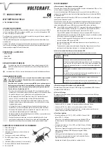
Connect the micro-USB connector (8) of the USB power meter to the USB power adapter, for
example. If necessary, use the provided USB cable.
If your USB-AC adapter has a cable with a micro-USB connector (such as the power supply
of a smartphone), you can plug it straight into the micro-USB connector (8) of the USB power
meter.
Alternatively, a USB port on a USB hub or a PC may be used as a source to supply voltage/
current.
Note that in any case the power consumption of the device used for measuring must not be
higher than what the power source (USB power adapter or the USB port of a USB hub or
computer) can deliver.
According to USB standard, a USB port on a USB 2.0/1.1 hub with power supply deliv-
ers a current of max. 500 mA. On the other hand, a USB port on a USB 2.0/1.1 hub
without power supply only delivers a current of max. 100 mA.
A modern USB 3.0 port of a computer or a USB 3.0 hub with power supply delivers
max. 900 mA. However, the output current of a notebook may also be less.
Beyond that, there are some USB ports that may deliver higher currents, such as the
USB charging port of a USB hub.
USB power supplies are available with an output current of 500 mA, 1 A, 2 A or more.
Therefore, please always follow the manual of the device which you are going to use as
a power supply. Do not overload the device!
b) Selecting the mode of the USB power meter
The desired mode can be set using the sliding switch (3).
Switch position Function
D
Data connection/data transmission is possible
Use this mode for measuring the power consumption of a USB stick, a
USB hard drive or other USB devices. During the measuring process a
data transmission is possible (USB 2.0/1.1).
I
Charging an Apple device (no data connection possible)
This mode is used to charge an Apple device (for example, an iPad
®
)
with a higher charging current.
S
Charging an Android device (no data connection possible)
This mode is used to charge an Android device (for example, a smart-
phone or tablet) with a higher charging current.
c) Connecting the device to the USB power meter
Connect the device which you intend to measure to the USB power meter’s USB-A connector
(5). Use the provided USB cable, if necessary.
d) Selecting the indicator
By repeatedly pressing button (4), you can select the desired indicator on the display (7).
• LED “V” is on: The measured voltage is shown in the display.
• LED “A” is on: The measured current is shown in the display.
• “AU” will briefly appear in the display: The measured voltage and the measured current are
then displayed alternately.
e) Special functions
• At excess voltage (> = 5.8 V), the display shows “SOS” and the LED
“V” goes on.
Never connect a device to the USB power meter when this is the
case; the high voltage can damage the device.
• At excess current (> = 3 A), the display shows “SOS” and the LED “A”
goes on.
In such a case the attached device draws too much current, which
may damage the USB power meter. Disconnect the USB device from
the USB power meter.
• The indicator automatically turns off after 8 minutes, if no changes in
current draw can be measured. Only the decimal point lights up.
Press button (4) to reactivate the display.
G
oPErATING INSTrUCTIoNS
PM-40 USB-PowEr-METEr
ITEM No. 1378822
INTENDED USE
The USB power meter is used to measure and display voltage and current at a USB port. For
this purpose, the USB power meter is connected between the USB port (e.g., a USB power
adapter or a computer) and the USB device.
That way you are able to control the charging current and the voltage while loading a smart-
phone or a tablet computer for example.
Always observe the safety instructions and all other information included in these operating
instructions.
This product complies with the applicable national and European requirements. All names of
companies and products are the trademarks of the respective owners. All rights reserved.
PACKAGE CoNTENTS
• USB power meter
• USB cable
• Operating instructions
EXPLANATIoN oF SYMBoLS
An exclamation mark in a triangle indicates important instructions in this operating
manual which absolutely have to be observed.
The “arrow” symbol is used where special tips and notes on operation are provided.
SAFETY INSTrUCTIoNS
The warranty will be void in the event of damage caused by failure to observe
these safety instructions! we do not assume any liability for any resulting
damage!
we do not assume any liability for material and personal damage caused by
improper use or non-compliance with the safety instructions! In such cases,
the warranty will be null and void.
• The unauthorised conversion and/or modification of the product is not permitted
for safety and approval reasons (CE). Never dismantle the product.
• The product is not a toy and does not belong in the hands of children.
• Never overload the product. For more information about the admissible voltage/
current range, see the chapter “Technical data”.
• The product must not be exposed to extreme temperatures, strong vibrations or
heavy mechanical stress. The product must not get damp or wet.
• The manufacturer does not accept any liability for incorrect or inaccurate readings
or any consequences resulting from such readings.
• Handle the product with care; it can be damaged by impacts, blows, or accidental
falls, even from a low height.
• Do not leave packaging material carelessly lying around. It may become a dan-
gerous plaything for children!
• If you are not sure about the correct operation or if questions arise which are not
covered by the operating instructions, please do not hesitate to contact our techni-
cal support or another specialist.
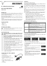
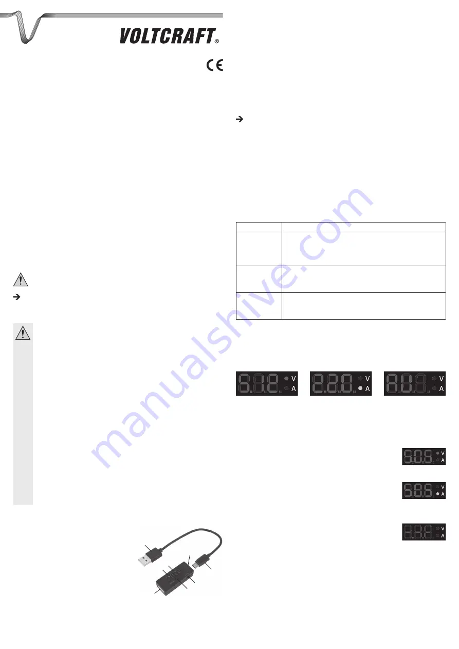
CoNNECTIoNS AND CoNTroL ELEMENTS
1 USB-A connector
2 Micro-USB connector
3 Sliding switch to select operating mode
4 Button to select display mode
5 USB-A connector (plug the measuring device in
here.)
6 LEDs for voltage (V) and current (A)
7 Display for measured value indication (voltage /
current)
8 Micro/USB jack
2
8
7
6
5
3
4
1
VErSIoN 10/15


