


500-003124-000
4-10
Once scanning is halted, any Data Register may be safely read as bytes except for
the Data Register pointed to by the Channel Pointer Register. Drawbacks to this
method is that it is inherently slow and the programmer loses a regular time reference.
The clock is stopped while the Halt bit is set (that is, the data is frozen for all channels
except the one pointed to by the Channel Pointer Register, whose input gets
converted constantly).
The other method to read the Data Registers as bytes, avoids interrupting
the regular automatic scanning process and thus preserves the conversion frequency
of all channels. This method requires the programmer to structure the code so the
two-byte accesses are guaranteed to be consecutive and uninterrupted. The Channel
Pointer Register must still be monitored and interrupts disabled to avoid accessing a
Data Register while the data is being updated preferably one should access a channel
immediately after it has been updated. Interrupts should always be disabled before
accessing a Data Register to avoid the possibility of a long interrupt service routine
coming between the two-byte accesses.
Of course, there are no problems if the Data Registers are accessed as a
single word, as recommended. For reference, however, the MSB of the data is in the
lower byte address while the LSB is in the higher byte address.
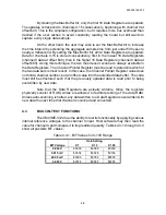
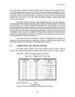
4.6
CURRENT INPUT -2BC AND -3BC OPTIONS
The -2BC option provides the current signal a 250
±0.01%, path to
ground. The -3BC option provides the current signal a 500
±0.01%, path to ground.
Table 4.6-1 shows the voltages seen by the ADC:
Table 4.6-1. Voltages Seen by the ADC
Current Range
(mA)
Termination
Resistor
ADC Voltage Input
(V
ADC
)
0 - 25
250
0 - 6.25 VDC
0 - 25
500
Not Recommended
0 -20
250
0 - 5 VDC
0 - 20
500
0 - 10 VDC
4 - 20
250
1 - 5 VDC
4 - 20
500
2 - 10 VDC
5 - 25
250
1.25 - 6.25 VDC
5 - 25
500
Not Recommended
Use the formula: I =
to convert the ADC readings to the actual current signal.
V
ADC
R
TERMINATION


