background image

EN - 4

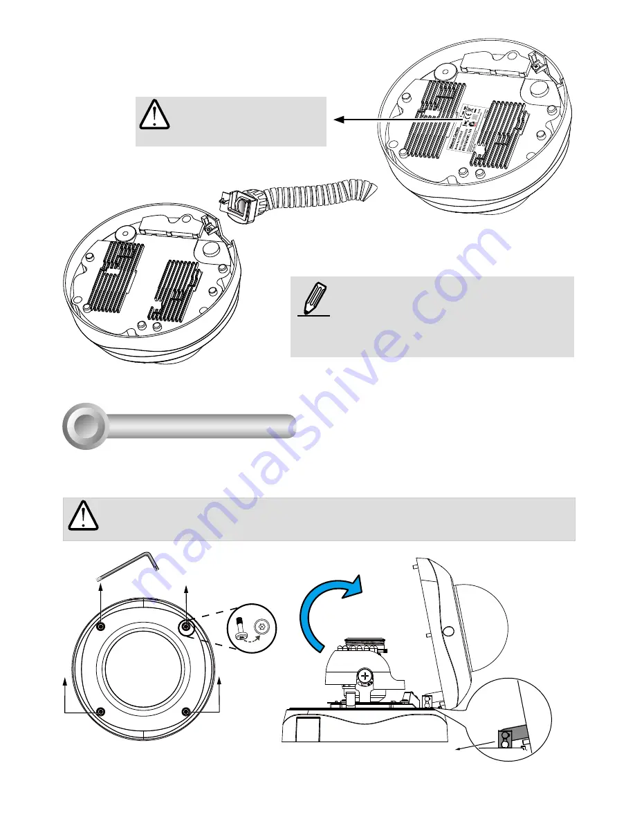
First, use the included T20 hex key wrench to loose the four screws and detach the dome cover from the 

camera base. Follow the steps below to install the camera either to a ceiling or a wall.

Hardware Installation

3

Top View

Dome Cover

Dome Cover Retainer

IMPORTANT!


Dome cover should be removed because if it should fall during the installation 

process, physical injury could occur to your co-workers. 

Record the MAC address 

under the camera base 

before installing the camera.

Replace the side opening cover with the 

included side outlet bushing if you want to 

route cables from the side of camera. The 1/2" 

protection conduits and tubing are separately 

purchased.


Содержание FD8335H

Страница 1: ......

Страница 2: ... in the event of occurrence Refer to your user s manual for the operating temperature Warning Before Installation Do not place the Network Camera on unsteady surfaces Do not touch the Network Camera during a lightning storm Do not insert sharp or tiny objects into the Network Camera Do not drop the Network Camera ...

Страница 3: ...stallation Guide Warranty Card Alignment Sticker Ceiling Hole Template Sticker Mounting Plate 510000221G Package Contents 1 L type Hex Key Wrench Moisture Absorber Screws Hex Nut Double sided Tape AV Cable Waterproof Connector Bushing ...

Страница 4: ...nd held monitor or camera tester with a BNC connector Press the button and use the focus and zoom adjustment pullers to tune the image until the BEST FOCUS message is shown Ethernet 10 100 RJ45 Socket Audio Video Out green Microphone In pink General I O Terminal Block Jumpers Microphone Video Output Internal External NTSC 60Hz PAL 50Hz 1 2 Micro SD SDHC Card Slot Reset Button Focus Assist Button L...

Страница 5: ...me Cover Dome Cover Retainer IMPORTANT Dome cover should be removed because if it should fall during the installation process physical injury could occur to your co workers Record the MAC address under the camera base before installing the camera Replace the side opening cover with the included side outlet bushing if you want to route cables from the side of camera The 1 2 protection conduits and ...

Страница 6: ...ower cables through the waterproof connector F E D B A as the illustration shows Then connect the power cables to the power source Note There are 8 holes on the seal D and the widest holes with a crack on the side are specific for power cables 4 If you have external devices such as sensors and alarms feed the cables through the Assembling Steps Sealing Nut A Housing B Seals C Seal D Screw Nut E He...

Страница 7: ... o O g B b G br BR 1 2 3 4 5 6 7 8 o white orange stripe O orange solid g white green stripe B blue solid b white blue stripe G green solid br white brown stripe BR brown solid 3 You will need an RJ45 crimping tool to attach the Ethernet wires to a connector When done connect the cable to the camera s Ethernet RJ45 socket 4 Press the Ethernet cable into the routing path at the bottom of the camera...

Страница 8: ...plastic anchors into the holes 3 Through three or four holes on the mounting plate insert the supplied screws into the corresponding holes and secure the mounting plate with a screwdriver 4 Feed the cables through the triangular cutout A or side opening B If you want to use hole B remove the side cover using a screwdriver Secure the camera base to the mounting plate with three supplied screws 5 Re...

Страница 9: ...supplied alignment sticker to the ceiling 2 Using the circle marks on the sticker drill at least 2 pilot holes symmetrically on each side into the ceiling Then hammer the four supplied plastic anchors into the holes 3 Through three or four holes on the mounting plate insert the supplied screws into the corresponding holes and secure the mounting plate with a screwdriver 4 Feed the cables through t...

Страница 10: ...transmission of power and data via a single Eth ernet cable Follow the below illustration to connect the Network Camera to a PoE enabled switch via Ethernet cable POWE R COLLIS ION LINK R E CE IVE PAR TITION 1 2 3 4 5 When using a non PoE switch Use a PoE power injector optional to connect between the Network Camera and a non PoE switch PoE Power Injector optional Non PoE Switch ...

Страница 11: ...e program 3 The program will search for VIVOTEK Video Receivers Video Servers and Network Cameras on the same LAN 0002D1083236 00 02 D1 08 32 36 192 168 5 109 FD8335H Installation Wizard 2 Assigning an IP Address 5 4 After a brief search the main installer window will pop up Double click on the MAC address that matches the one printed on the camera label or the S N number on the package box label ...

Страница 12: ...ment consisting of multiple cameras For its installation details please refer to its related documents Based on the live image retrieved from the camera adjust the camera lens by doing the following To adjust the viewing angle 3 axis mechanism design 1 Loosen the tilt adjustment screws and then turn the lens module up or down Upon completion tighten the screw 2 Turn the lens to adjust the image or...

Страница 13: ...ill find a moisture absorber bag attached to the dome cover Replace the moisture absorber included in the camera with the one shipped within the accessory bag W T 8 N To adjust the zoom factor and focus range 1 Loosen the zoom controller and then adjust zoom factor by moving the controller left and right Upon completion tighten the zoom controller screw 2 Loosen the focus controller and then adjus...

Страница 14: ......

Отзывы: