


VSC8211 Evaluation Board
User Guide
Revision 1.0
December 2013
Vitesse Proprietary
Page 10 of 13
3.1.2
Clock and Reset
Power must be applied and the clock (either 25MHz or 125MHz) must be active at the
correct frequency for the prescribed period of time in the datasheet before the RESETB
pin is released. PLLMODE and OSCDISB pins are sampled during the device power-up
or on assertion of RESETB pin.
The board will be shipped configured for use of the 25MHz crystal thus OSCDISB must
be pulled up and PLLMODE must be pulled down during power-up or assertion of
RESETB by setting J8 to the PLL enable position and holding SW-1 in the 25MHz
position upon power-up.
3.2
GUI and Driver Installation
Download the VSC8211EV GUI from Vitesse’s website onto a PC that has a USB port.
Install the GUI by launching the setup.exe file. Once installed, connect the USB cable
between the USB port of the PC and the USB connector (J20) on the evaluation board.
Ensure the MDIO and MDC jumpers are properly placed from DUT to F340 on J23 to
establish the connection between the VSC8211’s SMI pins and the SiLab F340.
USB communication is assisted by the Silabs USBXpress® drive. If not present on the
PC, the user will need to download the USBXpress Development Kit from the Silicon
Labs website (URL:
http://www.silabs.com/products/mcu/Pages/USBXpress.aspx
).
Follow the installation directions after downloading the development kit.
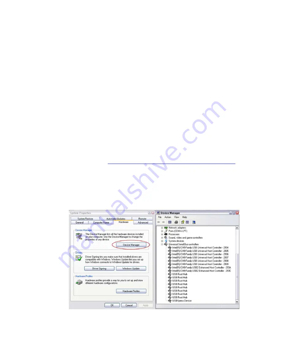
To ensure the USBXpress driver is installed and properly recognizing the evaluation
board, go to Control Panel and click on System>Hardware>Device Manager, and
inspect the Universal Serial Bus controllers listed to see if “USBXpress Device”
appears. Figure 3 shows that the PC recognizes that a USBXpress Device is connected.
Figure 3.
USBXpress as Seen From the Device Manager Window