background image

VITA - Vacumat 4000 Premium 

39/03/04 

Vita Zahnfabrik H.Rauter GmbH&Co.KG 79704 Bad Säckingen 

5

Installing the furnace and setting up for use 


2.1  Place for setting up 


Position the furnace in a dry, heated room in such a way that 

the minimum distance between all sides of the furnace and any 
wall should be at least 25 cm. 


In the case of temperatures under 15°C (e.g. after transport), 

leave the furnace to stand at room temperature for at least 30 
min. 

  Make sure the furnace is placed on a temperature-resistant 

surface. The radiant heat from the furnace, and the heat of the 
furnace itself are at a safe level. However, sensitive furniture 
surfaces and veneers may become slightly discoloured in time 
as a result of proximity to a constant heat source. 


Keep the furnace away from direct sunlight. 


Do not place any flammable objects near the furnace. 


Do not let the control panel come into direct contact with the 

heat radiating range of the furnace. 


2.2  Connecting the furnace to the mains power supply


Attention:

 please heed section 3, "Safety advice"! 


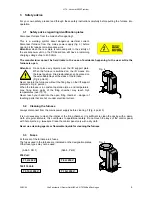
  Connect the furnace to the mains with the mains power lead 

supplied (Fig. 1). A suitable connecting cable is a cable type for 
heating apparatus, HO5RR-F 3G1, 0 mm

2

. Avoid using a 

junction box with extension cable - fire hazard in the case of 
overloading. 


Connect the vacuum pump (Fig. 1). 


Plug in the connecting cable of the control panel to the side of 

the furnace and open out (Fig. 2, point 1). 


Connect the connecting cable to the control panel (Fig. 3). 


Insert Smart media card into the drive. 


Switch on the furnace with the mains switch (Fig. 1, point 1), lift 

moves to lower position. 


Wipe the lift plate and the lift plate seal clean. (dust particles 

from the insulation resulting from transport of the furnace). 


Place the firing tray on the lift support plate. (Fig. 2,point 2). 


Put furnace into operation by pressing the 

Standby

 key (see 

also the section on standby operation). 


2.3  Switching off the furnace, putting out of operation 

When the furnace is not in operation the lift should be moved into the firing chamber and the furnace 
switched off at the mains switch (Fig. 1, point 2). Close the firing chamber to protect the insulation and 
prevent moisture. Close the lift by pressing the 

lift

 key. To switch off the furnace, press the 

finish

 key and 

confirm with the 

yes

 key. When the message 

END

 appears, the furnace can be switched off at the mains 

switch. 


Fig. 1 

1

2

3

4

5

6

1.  Tray for depositing hot objects 
2. Mains 

switch 

3. Vacuum 

connection 

4. Vacuum 

pump 

connection 

5.  Mains power connection 
6. Fuses


Fig. 2 

1

2

Fig. 3 


Connection, 15-polar 

Содержание vacumat 4000 premium t

Страница 1: ...VITA Vacumat 4000 Premium Operating Manual...

Страница 2: ...7 3 5 Ventilator 7 3 6 Mains power failure 7 4 Program parameters 7 5 Temperature rise 8 5 1 Vacuum display 8 6 Main menu 9 6 1 Button occupation within the writing modus 9 6 2 Activating ending Stand...

Страница 3: ...ndby temperature 17 9 2 Lift Speed 17 9 3 Signal time 18 9 4 Stop key 18 9 5 Operating hours 18 9 6 Operating hours firing 18 9 7 Unit no of furnace 18 9 8 Software version 19 9 9 Hotline 19 9 10 Temp...

Страница 4: ...d internal memory for approx 2000 firing programs external program memory card for firing programs of up to 10 users with max 200 programs each special accessories network connection Ethernet for inte...

Страница 5: ...rature monitoring vacuum monitoring power failure protection programme protection lift monitoring 1 6 Technical specifications width 240 mm depth 340 mm height 460 mm casing steel stainless steel weig...

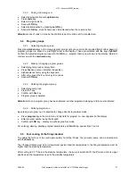
Страница 6: ...paratus HO5RR F 3G1 0 mm2 Avoid using a junction box with extension cable fire hazard in the case of overloading Connect the vacuum pump Fig 1 Plug in the connecting cable of the control panel to the...

Страница 7: ...le trays at the sides of the furnace Fig 4 point 2 Never operate the furnaces without the firing tray on the lift support plate see Fig 2 point 2 When the furnace is in constant operation max end temp...

Страница 8: ...and is not aborted during this time the display is out of action For your information the message Recover program interruption is shown in the display after the mains power is on again To clear this m...

Страница 9: ...ly entered in min sec If the pre drying temperature or the firing temperature is altered after entering the temperature rise rate the value C min is corrected the time in min sec remains as long as th...

Страница 10: ...ate sections for more details on these points Further functions of keys Direction keys up down for selecting a program group Direction keys right left for selecting program groups on the next or previ...

Страница 11: ...rature can be altered in the utilities program see section on utility programs 6 3 User menu This menu can accommodate up to 10 users Each user can store up to 200 firing programs and prevent unauthor...

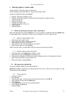
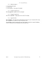
Страница 12: ...entry using the keyboard After entry press the cursor key to continue Save with OK key 6 4 3 Deleting the program group Select program group Press the key Confirm with Yes key Program group is deleted...

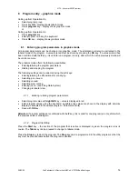
Страница 13: ...or indicates the position Alphanumerical entries using the keypad After entering continue by pressing the cursor key Store program names by pressing OK key Program name is stored and at the same time...

Страница 14: ...displayed 7 2 4 Changing to Operation On Press the key main menu program groups are now shown in the display 7 2 5 Program Start Stop Press the Start key the active section of the program is now shown...

Страница 15: ...eters Starting and stopping the program The following settings can be selected using the soft keys Entering altering the lift positions for pre drying Selecting pre vacuum Selecting vacuum Selecting s...

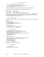
Страница 16: ...position 8 1 4 Selecting pre vacuum In the case of a program with vacuum the vacuum is built up in the firing chamber before the temperature rise begins Activating the vacuum Press the key Vor Vac pr...

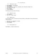
Страница 17: ...the keypad Save with OK key End with cooling key The following entry values appear in the display 8 1 8 Delete slow cooling Press cooling key Press key cooling is deleted 8 1 9 Entering job no It is o...

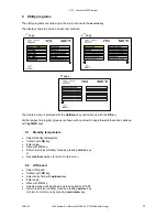
Страница 18: ...ft keys 9 1 Standby temperature Select standby temperature Confirm with OK key Enter value Store with OK key Return to service utilities menu by pressing service key or press main menu key to return t...

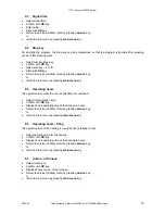
Страница 19: ...n menu key 9 5 Operating hours The operation time while the unit is switched on is recorded Select total operation time Confirm with OK key Display shows operating time of the furnace in hours Return...

Страница 20: ...ct measurements and hence to incorrect settings Select temperature adjustment display shows corrected value in the display Set value using the plus or minus keys Confirm with OK key Return to service...

Страница 21: ...elect automatic temperature adjustment Confirm with OK key Select with On Off key Save with OK key Return to utilities menu by pressing service key or return to main menu by pressing main menu key 9 1...

Страница 22: ...with the OK key 9 16 Date settings Select date settings Confirm with OK key Select field for entering Month Day Year format with up down key Enter values using the keypad Save by pressing OK key Retur...

Страница 23: ...essing service key or return to main menu by pressing main menu key 9 19 Languages Select languages Confirm with OK key Select desired language Store with OK key Return to service menu by pressing ser...

Страница 24: ...made to the PC The FDS system includes all the parts required for connection as well as the corresponding software and instructions for use 11 Smart Card disk The Smart Card supplied with the furnace...

Страница 25: ...e necessary to open the furnace for checking and remedying a fault Should this be the case please heed the safety instructions described in the section Safety advice The following error messages are s...

Страница 26: ...nt results have been obtained with alloys in conjunction with VITA Metal Ceramics OMEGA OMEGA 900 VMK 95 when the thermal expansion coefficient of the alloy measured in the range from 25 C 600 C corre...

Страница 27: ...0 6 00 9 00 61 1 050 2 00 0 00 VITAPRESS VITA OMEGA 900 IOV 500 6 00 8 00 60 980 2 00 8 00 GLAZE LT 400 4 00 4 00 90 760 1 00 0 00 VITAPRESS VITA OMEGA 900 CORRECTIVE 500 4 00 6 00 70 780 1 00 6 00 VI...

Страница 28: ...icient of the alloy measured in the range from 25 C 600 C corresponds to 14 0 14 4 x 10 6 x K 1 In the case of higher thermal expansion coefficients of the alloy the cooling phase of the temperature r...

Страница 29: ...g with VITA Akzent Fluid 600 4 00 4 00 85 940 1 00 Glaze firing with Akz 25 600 4 00 4 00 85 940 1 00 Additional firing programs Pre drying C min min C min Temp approx C min VAC min Spectra Gold 550 3...

Страница 30: ...5 K Key signal 21 L Languages 23 Lift positions for pre drying and cooling 8 Lift Speed 18 M Main menu 10 Mains power failure 7 Making changing program groups 12 O Operating hours 19 Operating hours f...

Страница 31: ...al ground and in as far as legally permissible is limited to the invoiced value of the goods supplied excluding turnover tax In particular as far as legally permissible we do not assume any liability...

Отзывы: