background image

www.vissonic.com 

  64    VISSONIC ELECTRONICS LIMITED 


White(off) 

Green(on) 

Applying to speak 
Please wait... 

Request to speak 

7.5  Default  Setting  On  VIS-DCP2000-W,  VIS-AP4C  and 

VIS-WDC-T/VIS-WDD-T 

Under the default setting on AP, main unit and delegate unit, the wireless conference system can 
work together automatically. If necessary, we set the whole system to default setting by following 
steps. 

Step 1

 Set the default setting on main unit VIS-DCP2000 

Menu->Default->Enter(Default) 

Step 2 

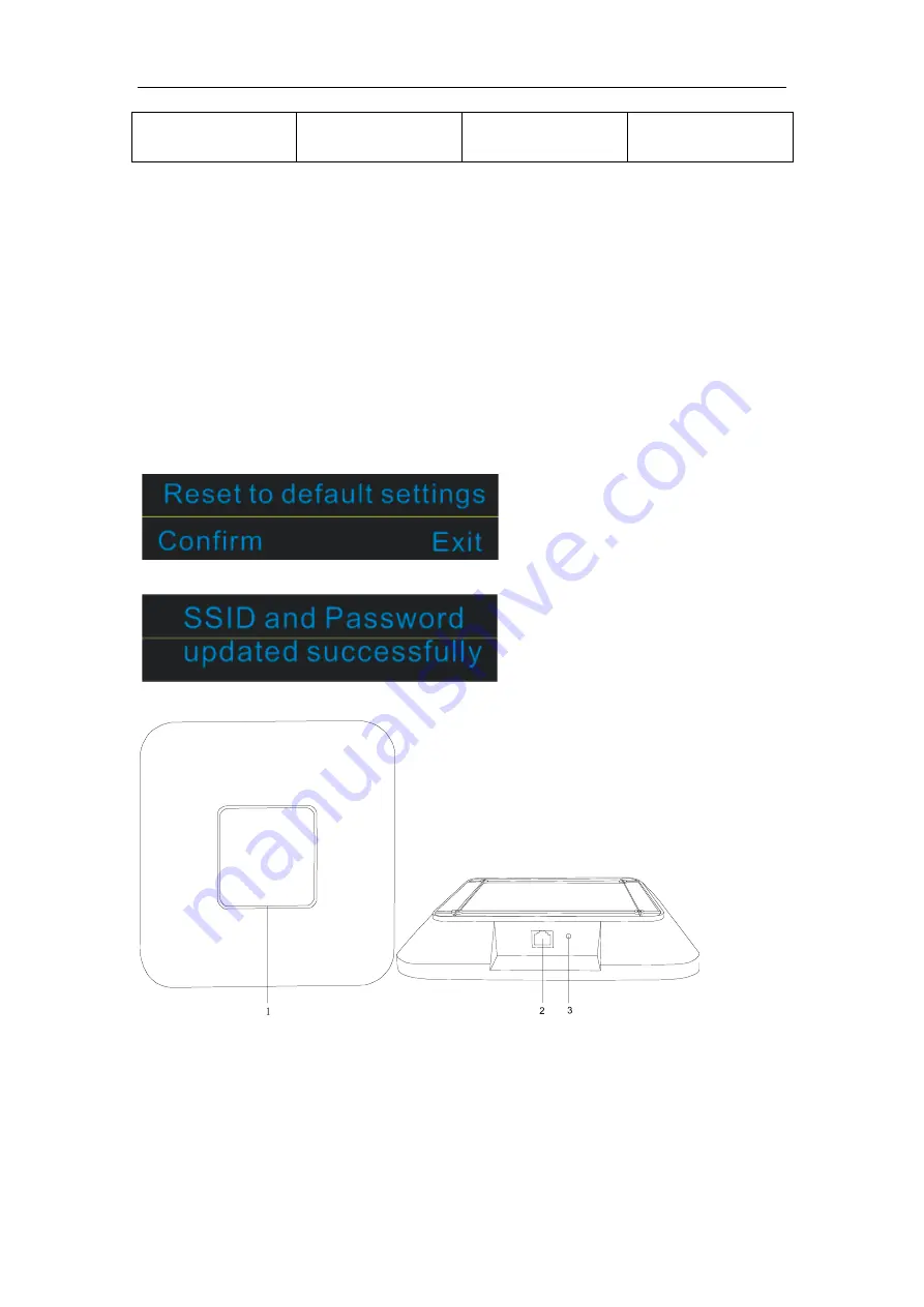
Press the volume - and + button at the same time when the unit reboot enter the bellowing 

interface.


Press 'ENTER' button to confirm and set it successfully. 


Step 3 

Set the default setting on the AP VIS-AP4C 


3.


Reset button   

Press the reset key on the back of the AP for about 10 seconds,The indicator is off,release the reset 
key .Press the reset key long again, the indicator light begins to flicker, and the AP has returned to 
the factory settings. 


Содержание CLEACON

Страница 1: ...www vissonic com 1 VISSONIC ELECTRONICS LIMITED CLEACON Full Digital Network DSP Conference system User Manual V1 3 9 Version VISSONIC ELECTRONICS LIMITED ...

Страница 2: ...dangerous voltage without insulation occurring within the equipment may cause people suffer from shock CE certification means that the product has reached the directive safety requirements defined by the European Union Users can be assured about the use of it SGS certification means that the product has reached the quality inspection standards proposed by the world s largest SGS This product passe...

Страница 3: ...em Attention in the wiring Only after cutting down all external power source can install wiring operation begin or it may cause electric shock or equipment damage This product grounds by the grounding wires To avoid electric shocks grounding wires and the earth must be linked together Before the connection of input or output terminal please make sure this product is correctly grounded Immediately ...

Страница 4: ...ple 28 2017 1 18 1 3 1 6 1 2 Zone Setup 25 2017 2 6 1 3 2 5 3 Audio outputs 18 2017 2 7 1 3 3 6 1 5 Camera Setup Example 28 Change the flow diagram 2017 3 11 1 3 4 Add WIFI model flush model 2017 6 21 1 3 5 6 3Configure the AP 7 5 Default setting 2017 6 27 1 3 6 Update manual for AP 2020 4 8 1 3 7 COM port definition connection 2020 7 17 1 3 9 Adding menu and POE 2022 4 22 ...

Страница 5: ...on 23 4 1 Install in the 19 rack 23 4 2 Install in the AP 24 4 3 Install in the Flush unit 24 5 Connection 25 5 1 Power supply 25 5 2 Audio inputs 25 5 3 Audio outputs 26 5 4 Audio Link 27 5 5 CU DU 27 5 6 AP 30 5 7 CONTROL 31 5 8 KEYBOARD 32 5 9 ETHERNET 32 6 Configuration 33 6 1 Configuration on the VIS DCP2000 W 33 6 1 1 DSP Menu 38 6 1 2 Zone Setup 38 6 1 3 Delegate Setup 41 6 1 4 Interpretati...

Страница 6: ...AP 51 6 4 Configure the AP VIS AP4C 53 6 4 1 Set up controller SSID and Password 53 6 4 2 Set up AP SSID and Password 56 7 Operation 61 7 1 VIS DCP2000 conference processor 61 7 3 Simple interpreter desk VIS DIC T 63 7 4 Chairman unit and delegate unit display and operation 63 7 5 Default Setting On VIS DCP2000 W VIS AP4C and VIS WDC T VIS WDD T 64 8 Install and Test 65 ...

Страница 7: ...age to the circuit Installation and wiring must be solid and reliable otherwise it may result in malfunction on device Make sure the device has been well connected to the ground before using Do not touch the terminals while power on or may cause electric shock malfunctions Do not disassemble the equipment without permission to avoid damage to the internal electrical components and will void the wa...

Страница 8: ...Point VIS AP4C Splitter Box VIS CNB Digital Array Microphone with channels selector Chairman Delegate Unit VIS ACC T VIS ACD T Digital Array Microphone Chairman Delegate Unit VIS DAC T VIS DAD T CAT5 Digital Discussion Chairman Delegate Unit VIS DCC T VIS DCD T CAT5 Digital Voting Chairman Delegate Unit with Channel Selector VIS DVC T VIS DVD T CAT5 Dual Channels Chairman Delegate Unit VIS DSC T V...

Страница 9: ... to all You can configure it by the button on front panel with screen information Figure 2 2 Front and rear view of VIS DCP2000 On front panel the processor unit contains 1 Power Switch Power on or off the processor unit 2 Display Show the current status or the result of your operation menu list etc 3 Operate Buttons 4 direction buttons for menu operation confirm and exit 4 Audio Recording Press t...

Страница 10: ...ote audio output OUT5 OUT6 OUT7 OUT8 is corresponding to the interpretation CH 1 CH2 CH3 CH4 13 Audio Link Extend to the next processor for conference room combination and audio exchange 14 CU DU It is used to connect delegate unit chairman unit translation unit or POE speaker Ring connection can be made between port 1 and port 2 or between port 2 and port 3 15 AP connect to 2 4GHz 5GHz Profession...

Страница 11: ...re delegate chairman units Figure 2 3 Front and side view of VIS EXM 1 Loop Through Chains Connect with processor unit last extension unit and next extension unit 2 Repeated Chains Provide 4 channels for delegate chairman units 3 Power indicator Indicate status of the power inlet connection 4 Power inlet Connect the extension unit with power cable ...

Страница 12: ...ng signal indicator When the AP is connected with power it will be static blue light When AP is communicating the indicator is flashing 2 Network port connect to the AP port of processor unit or POE switch 3 Reset button NOTE The switch do NOT recommend to other devices only connected with the main unit VIS DCP2000 and max 8 pieces of VIS AP4C ...

Страница 13: ... Repeated Chains spilt two chains for delegate chairman units 2 Loop Through Chains connect to the processor unit extension unit or loop to next connection box 2 5 CLEACON Digital Networked Delegate Chairman Unit Table models With the discussion units wired and wireless the delegates can make contribution to a conference ...

Страница 14: ...www vissonic com 14 VISSONIC ELECTRONICS LIMITED Figure 2 5 Top view of wired and wireless unit 1 ...

Страница 15: ...www vissonic com 15 VISSONIC ELECTRONICS LIMITED Figure 2 6 Top view of wired and wireless unit 2 ...

Страница 16: ...www vissonic com 16 VISSONIC ELECTRONICS LIMITED Figure 2 7 Side view of wired or wireless unit Figure 2 8 Side view of wired unit Figure 2 9 Side view of wireless unit ...

Страница 17: ...MITED Figure 2 10 Bottom view of wired unit Figure 2 11 Bottom view of wireless unit 1 Figure 2 12 Bottom view of wireless unit 2 1 Microphone socket Connects a pluggable gooseneck microphone VIS M600 VIS M410 or VIS M330 to the discussion units ...

Страница 18: ...r mute the system 7 Approval button Approve the applying microphone to be enabled under the apply mode and work as mute while pressed clear button 8 Volume button Adjust the earphone volume 9 Right channel selector Selects the channel that is sent to the right headphones 10 Left channels selector Selects the channel that is sent to the left headphones 11 Line in socket Connect the microphone mobil...

Страница 19: ...www vissonic com 19 VISSONIC ELECTRONICS LIMITED 2 6 CLEACON Modular Flush mounting models Figure 2 13 Top view of modular flush mounting units ...

Страница 20: ... 14 CU DU port for connecting between model VIS DCD F VIS DDC F VIS CSU F and main unit extension unit connection box etc 15 Screw hole for installation 16 FS bus for connecting model FS unit 17 SPK1 port to connect the VIS SPK F for working with current unit 18 MIC port connect to the model VIS DCC FS or VIS DCD FS and get the MIC input from model VIS DCC FS or VIS DCD FS 19 SPK2 port to connect ...

Страница 21: ...represents working status 2 High hardness speaker net built in 17 high pointing pickups 3 The switch button the chairman unit long press to start the priority mode you can turn off the representative unit 4 Headphone jack 5 Every two array units must be equipped with a VIS CNB as a connection box as shown in the following connection diagram ...

Страница 22: ...ge power supply while it has a basic control capacity with power relay devices it can load more devices Here we list a basic capacity of active units for one processor control unit Model Extension cable m VIS DCP2000 VIS EXM Port 1 Port 2 Port 3 Max total Port 1 Port 2 Port 3 Port 4 Max total VIS DCC T VIS DCD T VIS DIC T VIS DID T VIS DVC T 0m 30 30 30 90 30 30 30 30 120 05m 30 30 30 90 30 30 30 ...

Страница 23: ...e first unit to the VIS EXM 4 Installation 4 1 Install in the 19 rack The central unit can be installed in a standard 19 inch cabinet The unit has standard accessories of a pair of installation supports See the following diagram for installation NOTE Extension cable has direct effect on the control capacity The longer and extension cable you use the less power is available to drive the devices con...

Страница 24: ... Flush unit Installation steps 1 open the desktop corresponding to the size 2 install the embedded digital conference machine into the opened square hole of desktop 3 install the fixing plate on pressure riveting screw under the machine 4 fix the fixing plate with butterfly nut 5 making M5X35 the butterfly screws go through the fixing plate to lock with desktop so as to fix the equipment As below ...

Страница 25: ... 5 1 Power supply To connect the processor control unit to main power firmly Figure 5 1 5 2 Audio inputs The processor control unit provides RCA or XLR type audio input connector CAUTION Main power supply should well grounded otherwise it may cause fatal incident ...

Страница 26: ...al Shield Ground 4 Live Positive 5 Return Negative 5 3 Audio outputs The processor control unit provides RCA XLR or phoenix type audio output connector Figure 5 3 Audio output connection Pin Type Signal Description 1 Cinch Live Signal in 2 Return Shield Ground 3 XLR Xternal Positive 4 Live Shield Ground 5 Return Negative 6 Phoenix Positive 7 Negative 8 G Shield Ground ...

Страница 27: ...or better 5 5 CU DU Use the CU DU socket to connect to the chairman delegate unit or extension main unit and use the VISSONIC tested CAT5E cable or better There are three connection ways available for CLEACON conference system 1 Hand in Hand Loop Network is an important feature for CLEACON conference system You can use this connection way to make the system more steady ...

Страница 28: ...ITED Hand in Hand Loop Network connection is only available between channel 1 and channel 2 or channel 2 and channel 3 but not valid between channel 1 and channel 3 2 Hand in Hand Connection 3 Hand in Hand Connection Hand in Hand Loop connection ...

Страница 29: ...www vissonic com 29 VISSONIC ELECTRONICS LIMITED 4 Connction box Hand in Hand Loop connection 5 Extension Main Unit connection ...

Страница 30: ... AP socket to connect to the 2 4GHz 5GHz conference access point VIS AP4C or switch connected with VIS AP4C and use the CAT5 cable or better NOTE The switch do NOT recommend to other devices only connected with the main unit VIS DCP2000 and max 8 pieces of VIS AP4C ...

Страница 31: ...output 2V1 Switch the channel 2to output 3V1 Switch the channel 3 to output 4V1 Switch the channel 4 to output 14V1 Switch the channel 14 to output 15V1 Switch the channel 15 to output 16V1 Switch the channel 16 to output If you need other commands is needed to tell us for update the firmware Bottom COM connected to cameras or HD camera auto tracking controller VIS MSDI COM port pin is described a...

Страница 32: ...wer port of controller Pin Signal Description 1 Null 2 RXD Receiving data 3 TXD sending data 4 Null 5 GND Signal ground 6 Null 7 Null 8 Null 9 Null 5 8 KEYBOARD Use the KEYBOARD socket to connect to the Camera controller with CAT5 cable 5 9 ETHERNET Use the ETHERNET socket to connect to the PC and use CAT5 cable or better ...

Страница 33: ... to 4000 MIC mode Override Voice Open Apply and the maximum active number 1 2 4 6 Manu screen M e n u M I C M o d e The menu operation buttons ENTER and ESC is used to browse the menu and set the parameter 1 Press ENTER and ESC to browse the menu as the blue sign 2 Browse to the green sign menu 3 Press to adjust parameters and press the ENTER to confirm the options The knob Master vol is used to s...

Страница 34: ...www vissonic com 34 VISSONIC ELECTRONICS LIMITED ...

Страница 35: ...www vissonic com 35 VISSONIC ELECTRONICS LIMITED ...

Страница 36: ...www vissonic com 36 VISSONIC ELECTRONICS LIMITED ...

Страница 37: ... screen as bellowing M e n u M I C M o d e 2 Press the button M e n u A c t i v e M I C 3 Press the button ENTER A c t i v e M I C 1 1 2 4 6 4 Press the button to select the 6 A c t i v e M I C 1 1 2 4 6 5 Press button ENTER to confirm the option and the setting is done A c t i v e M I C 6 1 2 4 6 6 Press the button ESC back to the main menu U n i t 0 0 0 1 M I C O v e r r i d e 1 ...

Страница 38: ...ation 24dB is the highest noise cancellation AFC Lever 1 2 3 4 5 AFC Acoustic Feedback Cancellation used to prevent or suppress acoustic feedback the feedback energy can be divided into 5 levels AEC Enable On Off AEC Acoustic Echo Cancellation If the echo cancellation function is used it needs to be set to on and the input channel IN2 must be used to access the sound of the remote terminal and the...

Страница 39: ...etween X1 1 4000 then the microphone ID of zone 1 is X1 1 to X2 Zone 1 Gain Set the gain of the microphone in Zone 1 to output OUT2 mute Zone 2 Gain Set the gain of the microphone in Zone 2 to output OUT2 mute Zone 2 Gain Set the gain of the microphone in Zone 3 to output OUT2 mute Zone 4 Gain Set the gain of the microphone in Zone 4 to output OUT2 mute OUT3 ID zone Zone 1 Gain Zone 2 Gain Zone 3 ...

Страница 40: ...The audio of the remote input will not be mixed to this output and multiple selections can be made For example if the selected values are 1 and 4 the output channels OUT1 and OUT4 will not be mixed with the input audio output of IN2 Note DSP menu DSP Enable is turned on and AEC menu DSP DSP1 AEC is also turned on the remote output of OUT4 channel has AEC echo cancellation processing remote sound w...

Страница 41: ...kers and headphone on the delegate units Speaker On Off Turn on off the speaker on the delegate units not include the interpreter unit AGC enable On Off ANC enable On Off Reduce the noise for speaker and headphone on delegates Note Any noise reduction technology will affect the audio quality if customer pursue tone quality please set off the ANC EQ ID Select EQ Enable EQ1 EQ8 All On Off 00dB 12dB ...

Страница 42: ...auto tracking relative setting Menu item Parameter Value Description Protocol SAMSUNG PELCO D V ISCA CUSTOM VCA UDP Select the protocol according to the camera model The value CUSTOM mean the processor connect the camera tracking controller VIS MSDI and the preset information is saved on the camera controller and don t need to set the sub menu Camera map and Start Set Camera map Note If you use th...

Страница 43: ...ep 8 Repeat the step 2 step 6 to finish the camera 02 More camera are set as the same way Step 9 After setting the last microphone on and off the MIC we can adjust the camera to give a full view of the meeting and press ESC to quit from the menu of Start Set The preset of full view will be active while there are no microphone on Note When exit the camera setting the system will record the final ca...

Страница 44: ...tegrated computer to the upper control port of the CONTROL of the conference processing controller 1 RS232 controls HD camera automatic tracking controller VIS CATC A 2 RS232 control conference tracking and recording all in one machine VIS CRS05 A Step 3 Set the camera information to the main unit by the front panel and adjust camera to shoot the position by remote controller keyboard controller o...

Страница 45: ...IC ELECTRONICS LIMITED 6 1 6 Network Setup Use the menu items in Network sub menu to set the IP address and MAC for processor unit Menu item Parameter Value Description IP Option 1 000 to 255 Set the static IP for the processor ...

Страница 46: ...r can be adjusted according to the ID of the POE speaker and the volume of a maximum of 16 POE speakers can be adjusted Volume Select All POE Speaker Line out POE Speaker 1 to 16 All POE Speaker Select this item the knob on the front panel of the main unit will adjust the volume of the POE speaker Line out select this item the knob on the front panel of the controller will adjust the output volume...

Страница 47: ... off when scan set is on the system will check the ID of delegate units when boot up if there are ID conflict those conflicting MICs will be flashing Host Master Slave Slave Audi o Only When the conference system uses the connection structure of dual machine backup one conference processor can be selected as the master the other one is the slave and the slave audio output Slave Audio can be select...

Страница 48: ...tion units After connection all the units we need to set the ID for every contribution units If there are installed all VIS DIC T and need to set them as chairman unit delegate unit interpreter unit or VIP we need to set the unit type 6 2 1 Set the ID for the delegate chairman unit The LCD display are working on the main screen Main screen U n i t 0 0 0 1 M I C O v e r r i d e 1 Press the button E...

Страница 49: ...ll delegates A l l d e l e g a t e s T y p e A l l d e l Set as the above screen all the VIS DIC T are worked as the delegate units Next set the as Type ON O n T y p e O n We can check on the contribution units and the display on all units show the bellow screen Delegate We press the MIC button on the unitand the display will shift cyclically as Delegate Chairman interpreter VIP Let the them displ...

Страница 50: ...uter connects the network port of the upper layer of the AUDIO LINK with the network cable 6 3 2 change the IP segment of the computer Change the computer IP segment to 2 for example 192 168 2 200 Open the computer s network and Internet settings to change the adapter options Ethernet right click properties click on Internet protocol version 4 TCP IPv4 click on the properties below set the same IP...

Страница 51: ...ogin to AP 1 192 168 2 1 log on to AP through a computer browser to set up 2 Enter user name admin password admin 3 After logging in to the main interface click 5 8G Configuration on the settings navigation menu on the left 4 Click Setting 5 Click Scan As shown below ...

Страница 52: ...e the 5G signal usage in the field environment Channel shows the current AP WiFi_CONFERENCE occupation channel 48 and other AP occupation 5G channels 7 Click the return button to select the unused channel which is currently available between 36 48149 165 to select the unoccupied channel ...

Страница 53: ...ntroller menu and send it to all units 2 Log in to the AP and change the SSID of the AP 6 4 1 Set up controller SSID and Password 1 Enter the WIFI menu on the front panel of the conference controller LCD including the submenu SSID PASSWOPD Start Set Menu item Parameter parameter Describe SSID 16 bits 16 bit SSID default is WIFI_CONFERENCE PASSWORD 9 bits Communication password between 9 bit host a...

Страница 54: ...ommunicated For example we want to change the SSID to WIFI_VISSONIC and the Password to 88888888 2 The operational steps are as follows Step 1 Through the conference controller front panel LCD view and menu button operation press ENTER key to enter the option setting when the WiFi option is displayed turn down to display SSID PASSWORD Start set First set the SSID key to enter the setting to see th...

Страница 55: ... then the main opportunity sends the SSID and PASSWORD set by the step 1to the wireless conference unit and after the conference unit receives the information The display displays the Update succeeded Step 3 Shows that after the update is successful set up the Start set off and manually reschedule all microphone units all units display unable to connect to the controller constantly status at the A...

Страница 56: ...by 2 4g wifi or LAN as one of above connections Step 2 Open the computer s network and Internet settings to change the adapter options Ethernet right click properties click on Internet protocol version 4 TCP IPv4 click on the properties below set the same IP segment address for PC and AP The default IP address for the For example the network properties of our PC are as follows ...

Страница 57: ...in click Login login First click the Setting page under the navigation directory 5 8 G Configuration on the left side to set the wireless network name to be consistent with the SSID name set by the conference controller As shown in the figure multiple names can be set For example we add the name WIFI_VISSONIC After setting click Submit at the bottom of the page for 15 seconds for upload and saving...

Страница 58: ...k name we uploaded before in the figure set the wireless network password in the Share Key and finally click the Submit upload below to save the meeting unit has the display date and time that is the connection setting is successful Notes Wireless system Troubleshooting When there is noise from wireless unit internal speaker or external loudspeaker ...

Страница 59: ...all around 1 5 2 meters or mount on the center of ceiling DO NOT put the wireless unit too close to AP in one meter or too far away check the signal strength indicator on unit otherwise it will also cause noise because of the strong signal impact Coverage area All Wireless Devices need to be in the Wi Fi coverage area of the VIS AP4C we recommend AP install on ceiling of center of the room For a m...

Страница 60: ...www vissonic com 60 VISSONIC ELECTRONICS LIMITED Scan result like below there are 6 AP nearby channel is 48 52 36 157 161 ...

Страница 61: ... v e r r i d e 1 The screen will display as above picture including the information of total contribution units are connected to the system 0001 to 4000 MIC mode Override Voice Open Apply and the maximum active number 1 2 4 6 MIC mode On the main screen press the button and directly enter the sub menu of MIC mode to set the microphone mode When the conference processor is connected to the PC you a...

Страница 62: ...crophone Voice In the voice mode the unit will be activated by the voice and no need the press the MIC button Apply In the apply mode delegates can apply to enable their microphones with the microphone button on their contribution units and the green LED on MIC will be on When the chairman unit press the APROVAL button to enable the applying delegate microphone according to the applying order When...

Страница 63: ... show the volume level to speaker and headphone and press the volume buttons to adjust it Press the MIC button to turn on off the microphone Show the speaking time Digital clock show the current time Press the button and hold for mute for cough release the button to unmute 7 4 Chairman unit and delegate unit display and operation Microphones The colors of the LEDs of the microphone buttons the LED...

Страница 64: ...t setting by following steps Step 1 Set the default setting on main unit VIS DCP2000 Menu Default Enter Default Step 2 Press the volume and button at the same time when the unit reboot enter the bellowing interface Press ENTER button to confirm and set it successfully Step 3 Set the default setting on the AP VIS AP4C 3 Reset button Press the reset key on the back of the AP for about 10 seconds The...

Страница 65: ...ys Initializing After 3 seconds the main screen menu is displayed Main screen U n i t 0 0 0 1 M I C O v e r r i d e 1 The main screen is shown in the figure above including the number of conference microphones connected online 001 4000 the current mode of discussion Override first in first out Voice voice control Open open Apply application maximum number of delegates 1 2 4 6 At 1 2 there can be 1...

Страница 66: ...rameter 6 A c t i v e M I C 1 1 2 4 6 5 Press ENTER to confirm the current parameter 6 and make the parameter take effect displayed as ActiveMIC 6 A c t i v e M I C 6 1 2 4 6 6 Press ESC to return to the home screen U n i t 0 0 0 1 M I C O v e r r i d e 1 3 Change the AP band according to the field wireless network environment For specific operations see 6 3 AP band configuration ...

Отзывы: