background image


Quantum Receiver User Manual 


Web GUI Screens 


Issue No: A 


Page: 41 


Ref: ?-Insert_Document_Part_No._Here-? 

Copyright © 2021 Vislink is a Vislink Technologies Inc. companies 


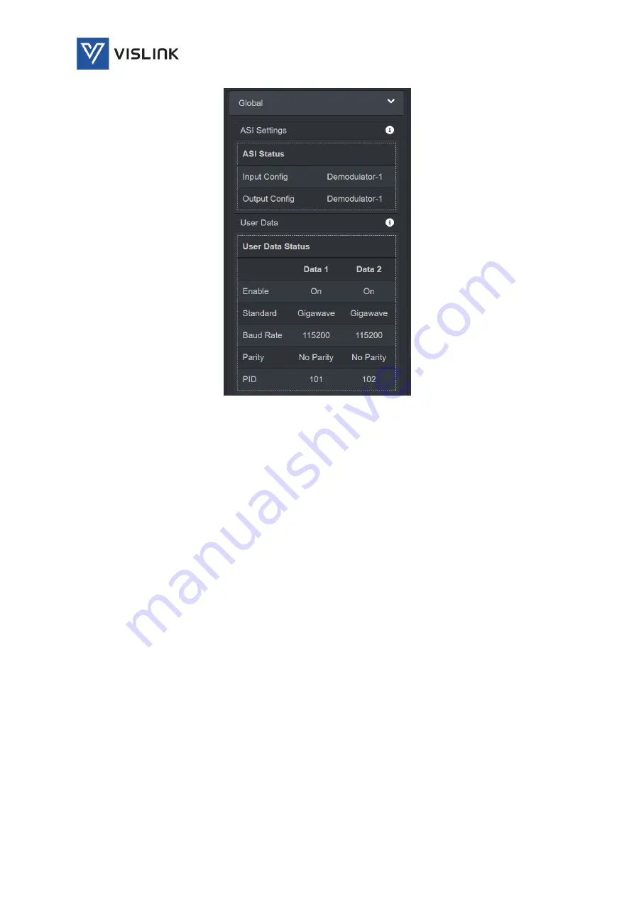
Figure 6-27 

Status>Global – More Information 

6.3.


Settings 

Clicking on the Settings menu enables detailed settings to be displayed in the 
central panel of the screen. 

6.3.1.


RF 

The Settings>RF panel details the settings for the unit to receive signals on the 
RF inputs. 

The RF panel provides further tabs for configuration of Modulation, Channel 
Plan and BDC. 

6.3.1.1.


Modulation 

The Settings>RF>Modulation tab specifies the modulation settings for the 
signals received on the RF inputs. 

Содержание Quantum

Страница 1: ...4 0 1442 431300 Facsimile 44 0 1494 775356 Email sales vislink com Website www vislink com Company Registered in England Wales no 10523708 VAT registration no GB 260 012 169 Registered Office Waterside House Earls Colne Business Park Colchester Essex CO6 2NS UK Quantum Receiver User Manual ...

Страница 2: ...d any additional Trademark content from external companies from their websites trademark pages etc Conventions NOTE Notes show to convey additional information CAUTION Cautions show where potential equipment damage could occur WARNING Warnings show where there is potential for personal danger or risk of death Read all warnings and understand them before carrying out work on any equipment This incl...

Страница 3: ...iii Ref Insert_Document_Part_No _Here Copyright 2021 Vislink is a Vislink Technologies Inc companies Document History Version Date Modification Firmware Version 1 00 30 09 2021 First release of document QANT 0100 00 06 ...

Страница 4: ... Video Audio Parameters 17 4 Rear Panel Connectors 18 4 1 RF Input Connectors Demod Cards 18 4 2 ASI Genlock Connectors 18 4 3 Video Monitoring Output Connectors 19 4 4 Audio Output Connectors 20 4 5 EXP Connectors 20 4 6 Focal Point Connector 21 4 7 Return Data Connector 22 4 8 Ethernet Transport Stream Control Connectors 22 4 9 USB Port Connectors 23 4 10 AC Power Connector 24 5 Front Panel Disp...

Страница 5: ...6 3 3 2 RTSP 51 6 3 3 3 UDP 52 6 3 3 4 SRT 53 6 3 4 eLinks 54 6 3 5 Presets 55 6 3 6 Network 56 6 3 6 1 Network 1 2 56 6 3 6 2 Active Directory 57 6 3 6 3 Tools 59 6 3 7 Global 60 6 3 7 1 ASI 61 6 3 7 2 Decryption 61 6 3 7 3 User Data 62 6 3 8 Admin 63 6 4 Info 63 6 4 1 Unit Information 63 6 4 2 License Information 65 6 5 Accounts 67 6 5 1 Users 67 6 5 2 Add New Account 67 7 Receiver Installation ...

Страница 6: ... Front Panel 25 Figure 5 2 Touch screen Display 25 Figure 5 3 Front Panel Home Screen 26 Figure 5 4 Front Panel Setup Screen 26 Figure 5 5 Front Panel Info Screen 27 Figure 5 6 Front Panel Status Screen 27 Figure 6 1 Web GUI Overview 28 Figure 6 2 Main Menus 28 Figure 6 3 Options Menu 29 Figure 6 4 Streaming Video 29 Figure 6 5 Streaming Video Options 30 Figure 6 6 Streaming Video Panel Control St...

Страница 7: ...gs Stream SRT Change Pass Phrase 54 Figure 6 40 Settings eLinks 54 Figure 6 41 Settings Presets 55 Figure 6 42 Settings Presets Create New Preset 55 Figure 6 43 Settings Presets Import New Preset 56 Figure 6 44 Settings Network Network 1 2 56 Figure 6 45 Settings Network ActiveDirectory 58 Figure 6 46 Settings Network Tools 60 Figure 6 47 Settings Global ASI 61 Figure 6 48 Settings Global Decrypti...

Страница 8: ...Pinout 19 Table 4 3 Video Monitoring Output Pinout 20 Table 4 4 Audio Pinout 20 Table 4 5 EXP Pinout 21 Table 4 6 Focal Point Pinout 21 Table 4 7 Return Data Pinout 22 Table 4 8 Ethernet Pinout 23 Table 4 9 USB Pinout 24 Table 4 10 AC Power Pinout 24 Table 6 1 Role Type Restrictions 59 Table 7 1 DVB T Bitrates 72 Table 7 2 LMS T Bitrates 72 ...

Страница 9: ...ts must not be cut broken apart incinerated or chemically processed In the case of Beryllium Oxide a white ceramic material the principal hazard is from the dust or fumes which are carcinogenic if ingested inhaled or entering damaged skin Please consult your local authority before disposing of these components CAUTION Tantalum Capacitors When subjected to reverse or excess forward voltage ripple c...

Страница 10: ...opted differ throughout the world and are from time to time re issued with revised guidelines For Vislink use when calculating minimum safe working distances apply a maximum power density limit w of 1w m Appendix A refers WARNING Any transmitting equipment radiating power at frequencies of 100 kHz and higher has the potential to produce thermal and athermal effects upon the human body To be safe a...

Страница 11: ...vironment is defined as one in which the person subjected to the RF radiation may be unaware of and has no control over the radiation energy received The uncontrolled environment conditions can arise even in the best regulated operations and for this reason the limits defined for the uncontrolled environment have been assumed for the Vislink recommended limit Documents a and b also show the RF pow...

Страница 12: ...Quantum Receiver User Manual General Information Issue No A Page 12 Ref Insert_Document_Part_No _Here Copyright 2021 Vislink is a Vislink Technologies Inc companies This page is intentionally unused ...

Страница 13: ...y over IP fiber networks cutting out the requirement for additional video compression stages IP connectivity enables production teams to work wirelessly and remotely over IP fiber networks or the unmanaged internet facilitating efficient live video production workflows Figure 2 1 Quantum Receiver Overview The Quantum Receiver incorporates a touch screen interface APIs and a web browser application...

Страница 14: ...ining of two ASI streams to produce a stream with fewer errors than either input provides a flexible and extendable receiver system When External ASI Diversity is configured as the unit input Demod 4 is switched to external ASI so the 16 way RF input is reduced to 12 way plus external ASI and the external ASI cannot be packet switched Packet switching is only possible if the external ASI is suppli...

Страница 15: ...companies 2 5 Licensed Options Various licenses are available to add functionality to the base configuration Licensed options are QANT LICE 0001 H 264 QANT LICE 0002 HEVC QANT LICE 0003 4K UHD QANT LICE 0004 Dual HEVC For further information about licenses and how they can be purchased delivered installed and enabled see Section 8 Licenses Upgrades ...

Страница 16: ...r demod card Up to 4x demod cards per unit Packet switching diversity between demod cards Frequency Band 100MHz 1000MHz Use in conjunction with the L3025 series down converters FEC 1 2 2 3 3 4 5 6 7 8 Guard Interval 1 32 1 16 1 8 1 4 Frequency Selection Up to 64 pre set channels or tuning in 1MHz steps via front panel control Demodulation DVB T LMS T Demodulation Modes QPSK 16QAM 64QAM Bandwidth D...

Страница 17: ...HD 6G SDI SMPTE 2081 12G SDI SMPTE 2082 Video Formats 480i 29 97 576i 25 720p 50 59 94 60 1080i 50 59 94 60 1080p 23 98 24 25 29 97 30 50 59 94 60 2160p 23 98 24 25 29 97 30 50 59 94 60 Audio Decoder Profiles AAC AAC LC HE AAC MPEG 1 Layer 1 Layer 2 Linear PCM Passthrough Audio Outputs Digital Up to 8x stereo pair Embedded audio over SDI Analogue 2x stereo pair Genlock CVBS Black Burst Tri level s...

Страница 18: ...s four RF input coaxial connectors for receiving UHF input 70MHz to 860MHz NOTE These inputs can have up to 24VDC output enabled in Unit LNB Power to power the external down converter limited to 400mA per connector short circuit protected Figure 4 2 RF Input Connectors Connector Legend Description 4x Plug in Cards each with 4x RF Connectors RF1 RF4 75 Ω BNC F Table 4 1 RF Input Pinout 4 2 ASI Genl...

Страница 19: ...xial connector to synchronize camera frame capture accurately aligning video and audio sources Figure 4 3 ASI Genlock Connectors Connector Legend Description 1x ASI Input Connector ASI IN 75 Ω BNC F 1x ASI Output Connector ASI OUT 75 Ω BNC F 1x Genlock Connector GENLOCK 75 Ω BNC F Table 4 2 ASI Genlock Pinout 4 3 Video Monitoring Output Connectors The unit provides four small form factor pluggable...

Страница 20: ...put Connectors Two 5 pin Lemo connectors with a audio pair per connector 2 x pairs 4 x channels 48kHz sampling Clip level 18dB THD 0 1 20Hz to 18kHz 0 25dB Crosstalk 60dB minimum Signal to noise ratio 66dB RMS Standard cable assembly part number L0079 Figure 4 5 Audio Connectors Connector Legend Description 2x 5 Pin Lemo Socket AUDIO1 AUDIO2 Pin 1 Left Line Line Pin 2 Left Line Return Pin 3 GND Pi...

Страница 21: ...ded for connection to the FocalPoint wireless camera control FocalPoint ODU Tx Head Serial data from the camera is returned via the transmitter as part of the MPEG transport stream in a similar way as the RS232 User data It is then extracted from the transport stream by the decoder and passed back to the transmitter via this connector Figure 4 7 Focal Point Connector Connector Legend Description 1...

Страница 22: ...r Tally Red Green Wet Dry Figure 4 8 Return Data Connectors Connector Legend Description 2x 15 Pin D F OCP USER TALLY 1 2 Pin 1 12V DC Pin 2 RS422 TX RS485 Pin 3 RS422 TX RS485 RS232 TX Pin 4 RS422 RX RS232 RX Pin 5 RS422 RX Pin 6 TTL RXD Pin 7 TTL TXD Pin 8 G TALLY DRY Pin 9 G TALLY WET A Pin 10 G TALLY WET B Pin 11 GND Pin 12 GND Pin 13 R TALLY DRY Pin 14 R TALLY WET A Pin 15 R TALLY WET B Table...

Страница 23: ...application To configure the unit via the web page see Section 7 5 Accessing the Web GUI for instructions on how to connect to the receiver and use the web browser LAN LAN PoE Video Over IP Standard 10 100 1000 Ethernet connection for streaming encapsulated Transport Streams into and out of the unit Only UDP encapsulation is supported LAN ports may also be used for control of the unit using the We...

Страница 24: ... Legend Description 2x USB 2 0 Interfaces USB 2 0 Standard USB 2 0 Table 4 9 USB Pinout 4 10 AC Power Connector A standard IEC 3 way connector is provided for the 100 240V AC power supply A 1 5A fuse is fitted integrally to the socket Figure 4 11 AC Power Connector Connector Legend Description 1x IEC Connector 100 240V AC 50 60Hz Live Neutral Earth Table 4 10 AC Power Pinout ...

Страница 25: ... movement or increment decrement of values options The knob may also be used as a push button to select highlighted screen functions 5 1 2 Headphones Socket The headphones socket is for future use 5 1 3 USB Port The USB Port is for future use and should not be used 5 1 4 Touch screen Display The screen displays status messages on the extreme left and provides touch screen buttons of Home Setup Inf...

Страница 26: ... button displays the status and quality in of the RF inputs as a colored bar On the extreme right hand side of the display the associated mode frequency bandwidth constellation and type are displayed Settings cannot be edited from this screen to edit use the Setup screen Figure 5 3 Front Panel Home Screen 5 3 Setup Touching the Setup button displays detailed settings on the right hand side of the ...

Страница 27: ...is a Vislink Technologies Inc companies Figure 5 5 Front Panel Info Screen 5 5 Status Touching the Status button displays detailed settings on the right hand side of the display Demod Rx Decoder Streams Network Analog Settings cannot be edited from this screen to edit use the Setup screen Figure 5 6 Front Panel Status Screen ...

Страница 28: ... 1 Web GUI Overview 6 1 1 Menus By selecting each of the main menus the central panel will display further relevant detail while the sidebars will continue to display the selected options Figure 6 2 Main Menus Four main menus are available Status enables selection of status information to be displayed in the left and right hand sidebars see Section 6 2 Settings enables selection and display of det...

Страница 29: ... be displayed Light Theme enables a light white background version and mainly black grey text to be displayed Logout enables the user to log out from their account A new user will be required to log in or create an account 6 2 Status Clicking on the Status menu enables further status related detail to be displayed in the central panel of the screen Status panels in the left and right hand sidebars...

Страница 30: ...ming Video Panel Control Status The Control Status buttons are Channel Number 2 identifies the channel being viewed Status Started displays the status of the channel usually Started when being viewed played Resolution 400 x 224 displays the resolution of the channel being viewed Minimize enables the selected main larger channel to be minimized Maximize Full Screen enables the selected channel to b...

Страница 31: ...a Status Options The Antenna Status options are Graph View enables disables a detailed graph showing either Quality RSL dBm or MER dB in the central panel for each of the four channels Source enables disables display a graph of either Quality RSL dBm or MER dB for each of the four RF channels Radar View enables disables the radar view displaying just the graph view Figure 6 9 Antenna Status Graph ...

Страница 32: ...ns for antenna status graphs Figure 6 11 Status Antenna Status Graphs Options The Antenna Status Graphs options are options can be set individually for each of the displayed bars in the graph Off enables the second other bar to be removed from the display MER dB displays a real time bar chart of the Modulation Error Ratio MER for each of the four channels range 15 25dB RSL dBm displays a real time...

Страница 33: ...a being measured for monitoring analysis over a period of time The data displayed starts at the time the option is selected or when the Reset button is clicked with each channel being shown as a different colored line This graph may be output as a file by clicking the Export button and selecting the storage location The graph may be filtered to display either just the most recent Last Minutes or a...

Страница 34: ...on preset are displayed in the right hand sidebar see Section 6 2 5 Figure 6 14 Status Active Preset Selection By clicking on the drop down menu you can select any of the configuration presets that have been previously saved 6 2 5 Active Preset Configuration Settings RH Sidebar The Active Preset panel displayed in the right hand sidebar displays the selected configuration preset for the receiver t...

Страница 35: ...Status Modulation The Modulation panel displays the following settings Frequency displays the mode of frequency modulation either Direct manual set frequency or Channel Plan preset frequencies allocated a channel number and the frequency of the frequency modulation scheme Encryption Decryption display On Off status and the Key number being used Clicking displays further information about the modul...

Страница 36: ... the Connected Disconnected status of the demodulator Lock displays the Locked Not Locked status of the signal The receiver can only down convert and demodulate the RF input when carrier lock has been achieved MER dB displays the Modulation Error Ratio MER of the input signal Quality displays the quality value of the input signal RSL dBm displays the Receive Signal Level RSL of the input signal Cl...

Страница 37: ...e active decoder settings Figure 6 20 Status Decoder The Decoder panel displays the following settings Video displays the video profile being used Audio displays the audio coding standard being used Service displays the service decoder status Genlock display the generator locking status of the decoder Analog displays the analog audio output status Clicking displays further information about each o...

Страница 38: ...utput streaming settings Figure 6 22 Status Stream Out The Stream Out panel displays the following settings RTP displays the status of the Real Time Transport Protocol RTP RTSP displays the status of the Real Time Streaming Protocol RTSP UDP displays the status of the User Datagram Protocol UDP useful for low latency and loss tolerating connections SRT display the status of the Secure Reliable Tra...

Страница 39: ...tings Figure 6 23 Status Stream Out More Information 6 2 5 5 Network The Network accordion panel details the active network settings Figure 6 24 Status Network The Network panel displays the following settings Network 1 displays the IP address and status green connected red disconnected Network 2 displays the IP address and status green connected red disconnected Clicking displays further informat...

Страница 40: ...5 Status Network More Information 6 2 5 6 Global The Global accordion panel details the active global ASI and User Data settings Figure 6 26 Status Global The Global panel displays the following settings ASI Settings displays the Asynchronous Serial Interface ASI settings User Data displays the User Data settings Clicking displays further information about these settings ...

Страница 41: ...licking on the Settings menu enables detailed settings to be displayed in the central panel of the screen 6 3 1 RF The Settings RF panel details the settings for the unit to receive signals on the RF inputs The RF panel provides further tabs for configuration of Modulation Channel Plan and BDC 6 3 1 1 Modulation The Settings RF Modulation tab specifies the modulation settings for the signals recei...

Страница 42: ...activate a pre determined frequency setting created using the Channel Plan tab Using Channel Plans therefore is a quick way to apply or restore a frequency setting Direct Frequency kHz enables the RF frequency to be typed or incremented decremented using the buttons displayed by hovering over this field Modulation Type enables different modulation types to be selected from the drop down list LMS T...

Страница 43: ...F Channel Plan The Channel Plan tab enables the creation and storage of a channel plan a pre determined configuration consisting of the active modulation settings as selected in the Modulation tab The settings will not be actioned until the Save button has been clicked Frequency Plans Channel List a list of defined frequency plans or pre determined configurations for quickly implementing a new mod...

Страница 44: ...bles or disables Low Noise Block LNB power for the selected device 6 3 2 Decoder The Settings Decoder panel details the settings for the unit to decode input signals The Decoder panel provides further tabs for configuration of Low Latency Service Genlock and Analog 6 3 2 1 Low Latency The Settings Decoder Low Latency tab specifies the video and audio settings for low latency decoding From the came...

Страница 45: ...een below to enable careful selection to keep it as low as possible Figure 6 31 Settings Decoder Low Latency The Low Latency tab specifies latency affected settings for video and audio decoder The settings will not be actioned until the Save button has been clicked Video Decoder Settings Standard enables selection of the main video decoding standard from a drop down menu MPEG2 H 264 HEVC UHD H 265...

Страница 46: ...the detected video decoding format of the incoming video is displayed Delay enables selection of a Standard or Low system delay to help with smooth decoding of encoded streams HDR Mode enables selection of High Dynamic Range HDR options from the dropdown menu SDR HDR or Auto HDR removes the limitations presented by older video equipment and adds more data about brightness and color across a wider ...

Страница 47: ...vice Select enables selection of the service from those available in the incoming multiplex by program number or PID Program Number enables selection of the service program by typing or by hovering over the field and clicking the increment decrement buttons Video PID identifies the location of the selected service in the video PID PCR PID identifies the location of the selected service in the Prog...

Страница 48: ...llow easy switching from one source to another without disruption To do this input signals must be genlocked generator locked to a reference Typically a video signal which does not have picture information on it is used Figure 6 33 Settings Decoder Genlock The Genlock tab specifies the mode for generator locking synchronisation Decoder Genlock Settings Genlock Mode enables genlock to be set as Off...

Страница 49: ...crement decrement buttons Audio Level Right enables the audio level to be set in dBm for the right audio channel Type or hover over the field and click the increment decrement buttons 6 3 3 Stream The Settings Stream panel details the settings for the streaming output The Stream panel provides further tabs for configuration of RTP RTSP Real Time Streaming Protocol UDP User Datagram Protocol and SR...

Страница 50: ...icking on this button enables the creation of a new RTSP streaming connection FEC Rows specifies the number of Forward Error Correction FEC rows to be used FEC Columns specifies the number of Forward Error Correction FEC columns to be used RTP Stream List displays the status of each streaming connection and the output URL Streaming connections may be deleted by clicking on the icon or modified by ...

Страница 51: ... monitors transmission statistics and provide quality of service QoS feedback and aids synchronization of multiple streams RTSP allows viewers to remotely pause play and stop video streams via the Internet without the need for local downloads NOTE RTSP streams require that stream is added to the end of IP Address e g rtsp 127 0 0 1 554 stream Figure 6 36 Settings Stream RTSP RTSP Settings Enabled ...

Страница 52: ...it to make sure the recipient received them it continues sending the more packets This is sometimes called a best effort service Figure 6 37 Settings Stream UDP The UDP tab specifies the settings for UDP streaming UDP Settings Create New UDP Stream clicking on this button enables the creation of a new UDP streaming connection UDP Stream List displays the status of the stream and the output URL Str...

Страница 53: ...nt packet loss while delivering the low latency performance of UDP In addition SRT can bring together multiple video audio and data streams within a single SRT stream to support highly complex workflows without burdening the network administrators Figure 6 38 Settings Stream SRT The SRT tab specifies the settings for SRT streaming The settings will not be actioned until the Save button has been cl...

Страница 54: ...ettings Stream SRT Change Pass Phrase 6 3 4 eLinks The Settings eLinks panel provides a status indication for the internal links to the RF Demod Cards and a method of quickly connecting and disconnecting them Figure 6 40 Settings eLinks Demod Card connection may be modified by clicking on the relevant edit icon making the necessary changes and then clicking on the save icon ...

Страница 55: ...tools Manage Presets Preset List previously stored presets are listed and can be managed from this screen Either Rename Overwrite Recall or Delete Create New Preset enable you to create a new configuration preset give it a name and store the current active configuration settings Figure 6 42 Settings Presets Create New Preset Import Presets enable you to import presets from receivers Configuration ...

Страница 56: ...eset Export Presets enable you to export presets to another similar receiver When selected a cfg file is created and stored at a location specified by the user using the date as the file name 6 3 6 Network The Settings Network panel details the settings for networking 6 3 6 1 Network 1 2 The Settings Network Network 1 2 panel enables networking to be configured Figure 6 44 Settings Network Network...

Страница 57: ...Dynamic Host Configuration Protocol Dhcp automatically assigns IP addresses and other communication parameters to devices connected to the network eliminating the need for individually configuring network devices manually IP Address specifies the network IP address Subnet specifies the network subnet mask Gateway specifies the network gateway address DNS specifies the Domain Name System DNS for th...

Страница 58: ...ny s email and password Custom groups can be created enabled disabled and removed These groups can then be assigned to individual users in the accounts page If the user belongs to the All group or any enabled group at the time of logging in the system will allow access LDAP URL specifies the Lightweight Directory Access Protocol LDAP URL for the ActiveDirectory domain name server must include the ...

Страница 59: ...enter username12345 to log in NOTE Do not enter the symbol when setting the preset domain Access Control List Administrator specifies the users who have administrator access rights Operator specifies the users who have operator access rights Manager specifies the users who have manager access rights Role Type Restrictions Menu Administrator Manager Operator Viewer Status Feed Settings RF Decoder S...

Страница 60: ...omain enables entry of an email username for the selected group Password enables a password to be set for the user passwords must be Groups specifies the group which will be queried Query Groups enables the query of the groups database to be performed Query BaseDN dc xx dc xx enables a query to be performed Accounts specifies the account which will be queried Query Accounts enables a query of the ...

Страница 61: ...fitted all these options are available Only three Demod Cards can be fitted if Diversity and External ASI is configured Demod 4 will be disabled The settings will not be actioned until the Save button has been clicked ASI Settings Input Config specifies the ASI input signal from the drop down menu Diversity External ASI Diversity Ext ASI or Demodulator 1 Output Config specifies the ASI output sign...

Страница 62: ...de is selected the appropriate key must be entered via the Web Browser 6 3 7 3 User Data The Settings Global User Data panel enables configuration of the data presented to the OCP User Tally 1 and OCP User Tally 2 ports Figure 6 49 Settings Global User Data The User Data tab enables configuration of the following settings The settings will not be actioned until the Save button has been clicked Dat...

Страница 63: ...nel enables access to engineering settings A valid password is required for entry These settings are for factory use only Figure 6 50 Settings Admin 6 4 Info Clicking on the Info menu enables details to be displayed in the central panel of the screen for unit and license information 6 4 1 Unit Information The Info panel displays Unit Information as shown below Figure 6 51 Info Unit Information ...

Страница 64: ... assigned by the manufacturer to the unit for identification This address serves as an electronic serial number Clicking displays the WAN and LAN addresses for the receiver Figure 6 52 Info Mac Address More Information Model Number specifies the model of the receiver as assigned by the manufacturer Serial Number specifies the unique serial number of the receiver Clicking displays Decoder and Demod...

Страница 65: ..._Part_No _Here Copyright 2021 Vislink is a Vislink Technologies Inc companies Figure 6 54 Info Software Version More Information Temperature specifies the temperature in degrees C of the unit interior 6 4 2 License Information The Info panel displays License Information as shown below ...

Страница 66: ... license number as valid the appropriate feature will be enabled The symbol alongside the feature will change from unavailable to a check mark available Video Decode lists the range of video decoding features functions that are available licensed for use on the receiver Descramble lists the range of descrambling features functions that are available licensed for use on the receiver Demodulator lis...

Страница 67: ... shown below Figure 6 56 Accounts Users The Accounts panel displays the following user settings User List lists the users authorized to use the receiver and displays the role that they have been assigned Users be deleted by clicking on the Delete icon or modified by clicking on the Edit icon to edit the existing account Create New User enables the creation of a new user account described above 6 5...

Страница 68: ...the password to be confirmed by entering it again Role Type specifies a role for the user for example Administrator Manager Operato or Viewer as selected from the drop down menu Days Selector specifies daily access for the user Select the By Week Days button to allow access on certain days of the week Simply place a check mark in the box for the active days required Select the By Date Range button...

Страница 69: ...r local viewing or production of the video input Monitor Output connect the HD BNC connectors from the SFP modules in the required configuration for either 4x 3G SDI 2x 6G SDI or 1x 12G SDI out for local viewing or production of the video input Audio Output connect the Lemo connectors for stereo monitoring of audio Focal Point connect the Lemo connector for wireless camera control Return Data conn...

Страница 70: ...communications so should not be used for external communications 7 5 Accessing the Web GUI The web browser Graphical User interface GUI is designed to configure control and monitor the unit and can be run on any Personal Computer PC or laptop using a suitable web browser NOTE The front panel touch screen display provides limited control and monitoring of the unit when a PC or control system is una...

Страница 71: ...hs available are 3 4 5 6 7 8 10 12MHz In Dual pedestal mode the effective width is therefore double that This means that in some channel widths the system could be used in single or dual mode e g 1 x 10MHz or 2 x 5MHz The overall throughput will be the same but this allows the RF performance to be optimised for particular operating environments NOTE There is a short delay approx 10s after switchin...

Страница 72: ...ation Configure these settings using the Settings RF Modulation menu option see Section 6 3 1 1 Modulation 1 Set Frequency Mode to Direct or Channel Plan 2 Set the Modulation Type to LMS T Single or Dual 3 Set the Bandwidth to 3 12MHz Single or 6 24MHz Dual 4 Set Guard Interval to Auto 5 Set Polarity to Auto 6 Set Frequency as required The table below defines the corresponding gross bit rates for ...

Страница 73: ... required 4 Set system Delay as Standard or Low to help with smooth decoding 5 Set HDR Mode to Auto 6 Set the Output Format for the video stream either 2SI or Quad Split 7 Set the output required on Video Loss 7 10 Deinterleaving The Quantum Receiver has a licensable deinterleaving option to match the interleaving option in the Vislink transmitter This option adds an extra layer of error correctio...

Страница 74: ...ed preset in order that you can recall reinstate them quickly should changes be made to the configuration Save your configuration using the Settings Presets menu option 1 Click on the Create New Preset button A Create New Preset window will be displayed to enable you to save your current settings 2 Type in a descriptive name for your configuration 3 Click the Save button to save the configuration ...

Страница 75: ...ed ESN Electronic Serial Numbers and hardware serial numbers as requested on the webpage See Section 6 4 Info to locate electronic serial numbers Hardware serial numbers are located on the unit s chassis To verify which licenses are already installed and enabled on your unit see Section 6 4 2 License Information 8 3 Firmware Upgrades To upgrade the unit s firmware refer to the firmware release not...

Отзывы: