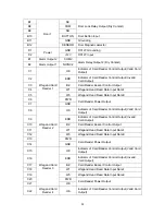
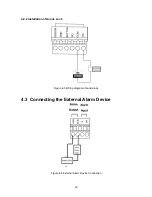
Visionis VS-AXESS-2D-ETL-PCB Скачать руководство пользователя страница 12

12 


C23 

ERR  

Indicator of Card Reader Control Output (Invalid 
Card Output)  

C24 

BZ  

Card Reader Buzzer Control Output  

C25 

W1  

Wiegand Head Read Data Input Data1  

C26 

W0  

Wiegand Head Read Data Input Data0  

C27 

PWR  

Card Reader Power Output  

C28 

OK  


  Note: 


The Alarm input hardware interface is normally open by default. So only the normally open 
signal is allowed. It can be linked to the buzzer of the card reader and access controller, 
and the alarm relay output and open door relay output.


For single-door access controller, the Wiegand card reader 1 and 2respectivelycorrespond 
to the entering and exiting card readers of door 1. For two-door access controller, the 
Wiegand card reader 1 and 2respectivelycorrespond to the entering and exiting card 
readers of door 1 , and the Wiegand card reader 3 and 4respectivelycorrespond to the 
entering and exiting card readers of door 2. For single-door access controller, the Wiegand 
card reader 1, 2, 3 and 4respectivelycorrespond to the entering card readers of door 1, 2, 3, 
and 4.


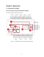
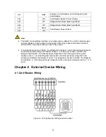
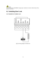
Chapter 4   External Device Wiring 

 
4.1 Card Reader Wiring 


Figure 4-1 Wiring diagram of Wiegand card reader


Содержание VS-AXESS-2D-ETL-PCB

Страница 1: ...1 Two Door Access Controller Panel Board TCP IP Wiegand with Software and Power Supply Included 10 000 Users VS AXESS 2D ETL PCB Installation Manual...

Страница 2: ...r TO THE MAXIMUM EXTENT PERMITTED BY APPLICABLE LAW THE PRODUCT DESCRIBED WITH ITS HARDWARE SOFTWARE AND FIRMWARE IS PROVIDED AS IS WITH ALL FAULTS AND ERRORS AND VISIONIS MAKES NO WARRANTIES EXPRESS...

Страница 3: ...undesired operation EU Conformity Statement This product and if applicable the supplied accessories too are marked with CE and comply therefore with the applicable harmonized European standards liste...

Страница 4: ...ow these precautions to prevent potential injury or material damage Tips The additional information as a complimentary of the contents Warnings Please adopt the power adapter from the legitimate facto...

Страница 5: ...on of Cathode Lock 12 4 2 2 Installation of Anode Lock 13 4 3 CONNECTING THE EXTERNAL ALARM DEVICE 13 4 4 DOOR BUTTON WIRING DIAGRAM 14 4 5 THE CONNECTION OF MAGNETICS DETECTION 14 4 6 CONNECTING POWE...

Страница 6: ...store 10 thousand legal cards and 50 thousand card swiping records Supports first card open function super card and super password function online upgrade function and remote control of the doors Supp...

Страница 7: ...7...

Страница 8: ...8 Chapter 2 Appearance 2 1 Component Description Access Controller Component Schematic Diagram The component schematic diagram is shown below Figure 2 1 VS AXESS 4D ETL PCB Component Schematic Diagram...

Страница 9: ...Description No Component Description VS AXESS 2D ETL PCB 1 Door Lock 1 2 Indicator 2 Power Indicator 3 Network Indicator 4 Jumper Cap for Restoring Factory Settings 5 Working Indicator 6 Alarm Output...

Страница 10: ...l Description Table 3 1 VS AXESS 2D ETL PCB Terminal Description No VS AXESS 2D ETL PCB A1 Alarm Input IN2 Alarm Input 2 A2 GND Grounding A3 IN1 Alarm Input 1 B1 Door 2 NC Door Lock Relay Output Dry C...

Страница 11: ...ard Reader Power Output C7 GND C8 Wiegand Card Reader 2 OK Indicator of Card Reader Control Output Valid Card Output C9 ERR Indicator of Card Reader Control Output Invalid Card Output C10 BZ Card Read...

Страница 12: ...pen door relay output For single door access controller the Wiegand card reader 1 and 2respectivelycorrespond to the entering and exiting card readers of door 1 For two door access controller the Wieg...

Страница 13: ...must connect the OK ERR BZ if using access controller to control the LED and buzzer of the Wiegand card reader 4 2 Installing Door Lock 4 2 1 Installation of Cathode Lock Figure 4 2 Wiring diagram of...

Страница 14: ...14 4 2 2 Installation of Anode Lock Figure 4 3 Wiring diagram of anode lock 4 3 Connecting the External Alarm Device Figure 4 4 External Alarm Device Connection...

Страница 15: ...15 4 4 Door Button Wiring Diagram Figure 4 5 Power Button Connection 4 5 The Connection of Magnetics Detection Figure 4 6 Magnetics Connection...

Страница 16: ...dware Steps 1 The jumper cap jumps from Normal to Initial 2 Disconnect the power and restart the access controller the controller buzzer buzzes a long warning 3 After the buzzer stops jump the jumper...

Страница 17: ...the parameters to the default setting and all the device events are wiping out 5 2 Relay Input NO NC 5 2 1 Lock Relay Output Lock Relay Normally Open Status Figure 5 2 Normally Open Status Lock Relay...

Страница 18: ...ormally Open Figure 5 4 Alarm Relay Output Normally Open Alarm Relay Output Normally Closed Figure 5 5 Normally Closed Status Work Flow of Software For detailed information please see the user manual...

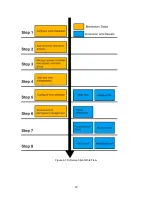
Страница 19: ...19 Figure 6 1 Software Client Work Flow...

Страница 20: ...r detecting the online device activating the device and resetting the password Get the SADP software from the supplied disk or the official website and install the SADP according to the prompts Follow...

Страница 21: ...heckbox of Enable DHCP 6 Input the password and click the Save button to activate your IP address modification STRONG PASSWORD RECOMMENDED We highly recommend you create a strong password of your own...

Страница 22: ...l the software according to the prompts Follow the steps to activate the control panel Steps 1 Run the client software and the control panel of the software pops up as shown in the figure below 2 Clic...

Страница 23: ...ton to start activation STRONG PASSWORD RECOMMENDED We highly recommend you create a strong password of your own choosing using a minimum of 8 characters including upper case letters lower case letter...

Страница 24: ...p up the Network Parameter Modification interface 9 Change the device IP address to the same subnet with your computer by either modifying the IP address manually or checking the checkbox of Enable DH...

Отзывы: