Visionary, Network Audio Video
23
D
UET
E-2/DuetD-2 U
SER
M
ANUAL
C
ONFIGURATION
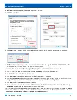
4. Enter a port number into to the STREAM.RTP_PORT filed.
a.
Must be an even number.
b.
Must be 1024 or above.
c.
If sending an RTP audio stream from more than 1 encoder, they must all use different port numbers.
5. Go the QSC Designer site design and add a Media Stream Receiver (MSR) object to the design.
6. In QSC Designer go to the File menu and select “Save to Core & Run”
7. Double-click to open the MSR object and enter the following link: http://<IP address of encoder>/audio.sdp
a.
Example: http://192.168.8.101/audio.sdp
•
The RTP audio stream will be transmitted from the encoder to the QSC Core DSP MSR.
V
IDEO
W
ALL
Multiple decoders can be grouped together to create a video wall. Setup involves assigning each decoder to its position in the video
wall. The decoders create a video wall by scaling the video content to a size that matches the full video wall.
When video walls are square (same number of rows and columns), the content will be scaled appropriately because the aspect ratio
is maintained. When video walls have a different number of rows and columns, the content will be stretched by the video wall
processor. Standard 16:9 content will appear wider or taller than normal. To maintain the proper aspect ratio on video walls that
have a different number of rows and columns, content should be custom created. The decoders also have the capability to rotate the
video output clockwise.
Note
: Check the
Zoom
settings on each display to get the best fit. Look for options like
Screen Fit
(Samsung),
Full Pixel
(Sony),
Dot-
by-Dot
(Sharp), or J
ust Scan
(LG). The effect of these preferences is to turn off HDMI Overscan.
The following step-by-step instructions describe how to configure a 2x2 video wall. As you change these parameters, the diagram
representing these settings automatically adjusts to provide you with a visual guide.
1. Access the web interface for each decoder unit that will be part of the video wall and log in with
username
=
admin
password
=
admin
.
2. Click the
Configuration
tab.
3. On each decoder:
a. Set
VW.ENABLED
to
True
on by selecting the check box.
b. Assign a user defined video wall name to each decoder that will be part of the video wall:
VW.NAME
.
Assign the same name to each decoder that will be part of the video wall you are creating. For example: Videowall_1. The
Vision Lite software uses this name to automatically group all of the decoders into a video wall object that can then have
sources routed to it in the Vision Lite drag and drop “routing” user interface.
c. Set the
VW.STRETCH_TYPE
. This option chooses how a video is scaled to the wall area. The default is
Fit
, which scales the
video to fit the wall area, changing the aspect ratio as needed.
d. Set the video wall rotation
VW.ROTATION
. Options are 0, 90, 180, or 270 degrees clockwise.
e. Set the Bezel and Gap settings:
VW.OVERALL_WIDTH, VW.VISIBLE_WIDTH
,
VW.OVERALL_HEIGHT
,
VW.VISIBLE_HEIGHT
.
Units = 0.1mm.
f. Set the Row and Column settings:
VW.MAX_ROWS
,
VW.MAX_COLUMNS
.
In this 2x2 video wall example, set the
VW.MAX_ROWS
to
2
and set the
VW.MAX_COLUMNS
to
2
.
g. Set the position on the video wall for the decoder to display:
VW.ROW, VW.COLUMN
.


