background image


of  the  8

th 

(9

th

/10

th

)  and  the  anode  of  the  9

th 

(10

th

/11

th

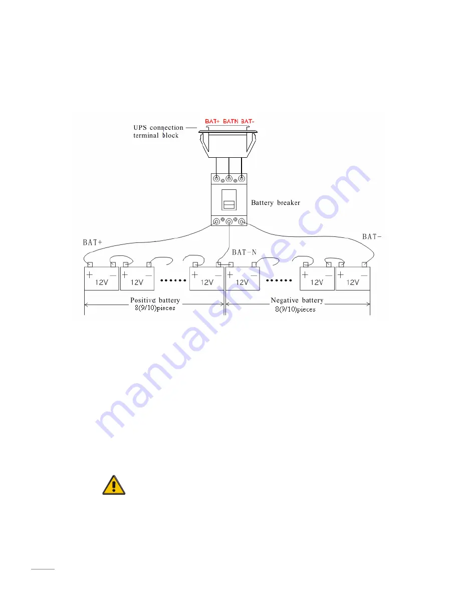
)  of  the  batteries.  Then  the  neutral, 

the  battery  positive  and  the  battery  negative  are  connected  with  the  UPS  respectively. 
The  battery sets between the Battery anode and the neutral are called positive batteries 
and that  between  neutral  and  cathode  are  called  negative  ones.  Users  can  choose  the 
capacity and the numbers of the batteries according to their demands. The connection is 
shown as following: 


Note

: 


The BAT+ of the UPS connect poles is connected to the anode of the positive 

battery,  the  BAT-N  is  connected  to  the  cathode  of  the  positive  battery  and 
the  anode  of  the  negative  battery,  the  BAT-  is  connected  to  the  cathode  of  the 
negative battery.


Factory default setting for battery quantity is 16pcs and for battery capacity is 

7AH  (charger  current  1A).  When  connecting  18pcs  or  20pcs  batteries,  please 
re-set  battery  quantity  and  its  capacity  after  UPS  starts  at  AC  mode.  Charger 
current  could  be  adjusted  automatically  according  to  battery  capacity  selected. 
(Also  charger  current  is  selectable).  Via  the  setting  tool,  all  related  parameter 
settings can be performed. These corresponding settings are done though LCD. 


CAUTION!


Ensure correct polarity battery string series connection. i.e. inter-tier 
and inter block connections are from (+) to (-)terminals. 
Don’t mix batteries with different capacity or different brands, or 
even mix up new and old batteries, either. 

Содержание Spirit II G XL

Страница 1: ...User Manual Vision Spirit II G XL 6 10KVA PF0 9 3 1 phase True online double conversion UPS ...

Страница 2: ...line UPS designed by our R D team who is with years of designing experiences on UPS With excellent electrical performance perfect intelligent monitoring and network functions smart appearance complying with EMC and safety standards This UPS has become standard product which meets the world s advanced level Read this manual carefully before installation This manual offers technical support for equi...

Страница 3: ... 1 Operation modes 12 4 2 Turn on off UPS 13 4 2 1 Connecting with utility 13 4 2 2 Black Cold start procedure 13 4 2 3 Inverter Off 14 4 2 4 Disconnecting with utility 14 4 3 LCD Display instruction 14 4 4 Working mode and transferring 16 4 4 1 Transfer to bypass if overload 16 4 4 2 Normal mode to battery mode 17 4 4 3 Go to bypass mode due to over temperature 17 4 4 4 Output short circuit 17 4 ...

Страница 4: ... is strongly poisonous and do harmful to body 4 Please avoid short circuit between anode and cathode of battery otherwise it will cause spark or fire 5 Don t disassemble the UPS cover or there may be an electric shock 6 Check if there exists high voltage before touching the battery 7 Working environment and storage way will affect the lifetime and reliability of the UPS Avoid the UPS from working ...

Страница 5: ...hich input current is kept in balance No unbalance problem might occur And also support for three phase input Digital Control This series UPS is controlled by Digital Signal Processor DSP ehance it increases reliability performance self protection self diagnostics and so on Battery Configurable from 16pcs to 20pcs The battery voltage of this series UPS can be configured at 16pcs 18pcs or 20pcs acc...

Страница 6: ... the appearance to see if the UPS is damaged or not during the transportation do not switch on the UPS if any damage found Please contact the dealer right away 3 Check the accessories according to the packing list and contact the dealer in case of missing parts 3 2 UPS module outlook Front View Rear View ...

Страница 7: ...D control panel 开机 关机 退出 旁路 故障 主路 逆变 输出 确认 LCD control panel introduction 1 LCD screen 2 ESC 3 OFF button 4 ON button 5 forward button 6 Enter 7 backward button 8 Output Indicator 9 Inverter Indicator 10 Battery Indicator 11 Mains AC Indicator 12 Bypass Indicator 13 Fault Indicator 3 4 Installation notes Please place the UPS in a clean stable environment avoid the vibration dust humidity flammable...

Страница 8: ...s range will reduce the battery capacity Should the equipment not be installed immediately it must be stored in a room so as to protect it against excessive humidity and or heat sources CAUTION An unused battery must be recharged every 3 months Temporarily connecting the UPS to a suitable AC supply and activating it for the time required for recharging the batteries are required The highest altitu...

Страница 9: ...les The cable design shall comply with the voltages and currents provided in this section Kindly follow local wiring practices and take into consideration the environmental conditions temperature and physical support media WARNING UPON STARTING PLEASE ENSURE THAT YOU ARE AWARE OF THE LOCATION AND OPERATION OF THE EXTERNAL ISOLATORS WHICH ARE CONNECTED TO THE UPS INPUT BYPASS SUPPLY OF THE MAINS DI...

Страница 10: ...tent operation Choose appropriate power cable and pay attention to the diameter of the connection terminal of the cable that should be greater than or equal to that of the connection poles Input connection 3phase 4wires ground WARNING If the load equipment is not ready to accept power on the arrival of the commissioning engineer then ensure that the system output cables are safely isolated at thei...

Страница 11: ...tery and the anode of the negative battery the BAT is connected to the cathode of the negative battery Factory default setting for battery quantity is 16pcs and for battery capacity is 7AH charger current 1A When connecting 18pcs or 20pcs batteries please re set battery quantity and its capacity after UPS starts at AC mode Charger current could be adjusted automatically according to battery capaci...

Страница 12: ...arallel system comprising of two or more UPS modules is the same as that of single module system The following sections introduce the installation procedures specified to the parallel system 3 9 1 Cabinet installation Connect all the UPSes needed to be put into parallel system as below picture Make sure each UPS input breaker is in off position and there is no any output from each UPS connected Ba...

Страница 13: ...ty of the control 3 9 3 Requirement for the parallel system A group of paralleled modules behave as one large UPS system but with the advantage of presenting higher reliability In order to assure that all modules are equally utilized and comply with relevant wiring rules please follow the requirements below 1 All UPS must be of the same rating and be connected to the same bypass source 2 The Bypas...

Страница 14: ...transfer the load from the inverter supply to bypass supply without interruption to the critical load In the event that the inverter output is not synchronized with the bypass AC source the static switch will perform a transfer of the load from the inverter to the bypass with power interruption to the critical AC load This is to avoid paralleling of unsynchronized AC sources This interruption is p...

Страница 15: ...d Bypass LED turn Green the inverter is starting up now When the inverter is checked normal the UPS goes to working mode and the load is supplied by the inverter now No matter the UPS is operated normally or not the LCD display will indicate current status The top lines display the UPS operational status and the bottom lines indicate alarm conditions when they occur 4 2 2 Black Cold start procedur...

Страница 16: ...th utility CAUTION This procedure should be followed to completely shut down the UPS and the LOAD After all power switches isolators and circuit breakers are opened there will be no output After the inverter is off turn the Utility and battery breakers to OFF then the LCD display will extinguish completely and fan stops spinning in 60 seconds If there are external battery packs connected please al...

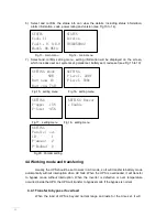
Страница 17: ...s by pressing 5 Select and confirm the data info to be viewed in detail It contains the details of the AC input output inverter battery BUS parallel temperature see Fig 4 to 12 below FIGURE Mains A 220 0 B 220 1 FIGURE Output 220 0V 0 0A FIGURE Output 0KW 0KVA C 220 0 50 0Hz 50 0Hz Load 0 Fig 4 Main input info Fig 5 Output info Fig 6 Output info FIGURE Invert 220 0V 50 0HZ FIGURE P Battery 0V 0 0A...

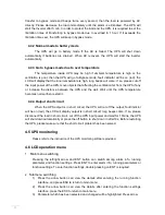
Страница 18: ...0Hz Fig 15 setting menu Fig 16 setting menu SETTING V upper 15 V lower 45 SETTING Buzzer Enable Fig 17 setting menu Fig 18 setting menu SETTING Parallel set ID 1 P amount 2 P Redund 0 Fig 29 Parallel setting 4 4 Working mode and transferring Usually the UPS should be set to work in AC mode so it will transfer to battery mode automatically without interruption when AC fails When the UPS is overload...

Страница 19: ...nd the wall Wait until the UPS temperature becomes normal then restart it 4 4 4 Output short circuit When the UPS output is in short circuit the UPS will cut off the output fault indictor will be on red the LCD will display output is in short circuit long beeps come If so please disconnect the load in short circuit cut off the UPS input power and wait for 10mins the UPS will shut down automaticall...

Страница 20: ...CD 1 If there is alarm but no valid operation on buttons the alarm info with top priority will be shown on LCD automatically 2 When there isn t any alarm and the LCD is displaying the submenu of running parameters such as output current these parameters will be always displayed on the LCD if no further operation on buttons If the LCD is not displaying the submenu of running parameters it will retu...

Страница 21: ...he UPS continuously during 24 hours in battery mode 3 Charge the battery every 3 months for at least 12 hours if the battery has not been used If the ambient temperature is high you have to charge it every 2 months 4 Check and clean the battery connections regularly on the models with long back up If autonomy time becomes much shorter than before or if a battery default is displayed on LCD then co...

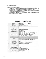
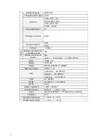
Страница 22: ...0 99 rating voltage 380 400 415VAC or 220 230 240VAC rating frequency 50Hz 60Hz auto sensing Voltage range 208 478VAC Frequency range 45 55Hz 54 66Hz Bypass voltage range 220Vac max 10 15 20 or 25 default 25 230Vac max 10 15 or 20 default 20 240Vac max 10 or 15 default 15 min 20 30 or 45 default 45 Bypass frequency range 1 2 4 5 10 THDI 3 100 linear load input THDV 1 5 100 non linear load input TH...

Страница 23: ...nd bypass 0ms unlock 15ms 50Hz 13 33ms 60Hz Norse 55dB 1m Display LCD LED Safety Meeting IEC62040 1 GB4943 Max input voltage 320Vac 1Hr EMI Conduction IEC 62040 2 Radiation IEC 62040 2 Harmonics IEC 62040 2 EMS IEC 62040 2 MTBF 250 000Hr 1 1 400 000Hr MTTR 30min Isolation resistance 2MΩ 500Vdc Isolation intension 2820Vdc 3 5mA 1min Surge Meeting IEC60664 1 1 2 50uS 8 20uS 6kV 3kA Protection IP20 P...

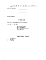
Страница 24: ...e port Pin 1 VCC Pin 2 D pin 3 D Pin 4 GND Application use UPSilon2000 Power Management software Available functions of the USB Monitor UPS power status Monitor UPS alarm info Monitor UPS running parameters Timing off on setting Appendix 3 Option 1 Dry contact card 2 SNMP card 3 Parallel card ...

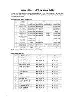
Страница 25: ...tor broken Beep continuously Fault LED lit 5 Bypass Thyristor short Beep continuously Fault LED lit 6 Bypass Thyristor broken Beep continuously Fault LED lit 7 Fuse broken Beep continuously Fault LED lit 8 Parallel relay fault Beep continuously Fault LED lit 9 Fan fault Beep continuously Fault LED lit 10 Reserve Beep continuously Fault LED lit 11 Auxiliary power fault Beep continuously Fault LED l...

Страница 26: ...ED blinking 29 Output Short circuit Once per second Fault LED blinking 30 Rectifier over current Once per second Fault LED blinking 31 Bypass over current Once per second BPS LED blinking 32 Overload Once per second INV or BPS blinking 33 No battery Once per second BATTERY blinking 34 Battery under voltage Once per second BATTERY blinking 35 Battery low pre warning Once per second BATTERY blinking...

Отзывы: