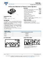


TSOP362..
www.vishay.com
Vishay Semiconductors
Rev. 2.3, 18-Oct-11
5
Document Number: 82187
THIS DOCUMENT IS SUBJECT TO CHANGE WITHOUT NOTICE. THE PRODUCTS DESCRIBED HEREIN AND THIS DOCUMENT
ARE SUBJECT TO SPECIFIC DISCLAIMERS, SET FORTH AT
www.vishay.com/doc?91000
SUITABLE DATA FORMAT
The circuit of the TSOP362.. is designed so that unexpected
output pulses due to noise or disturbance signals are
avoided. A bandpass filter, an integrator stage and an
automatic gain control are used to suppress such
disturbances.
The distinguishing mark between data signal and
disturbance signal are carrier frequency, burst length and
duty cycle.
The data signal should fulfill the following conditions:
• Carrier frequency should be close to center frequency of
the bandpass (e.g. 38 kHz)
• Burst length should be 10 cycles/burst or longer
• After each burst which is between 10 cycles and 70 cycles
a gap time of at least 14 cycles is necessary
• For each burst which is longer than 1.8 ms a
corresponding gap time is necessary at some time in the
data stream. This gap time should be at least 6 times
longer than the burst
• Up to 800 short bursts per second can be received
continuously
Some examples for suitable data format are: NEC code
(repetitive pulse), NEC code (repetitive data), Toshiba
Micom Format, Sharp code, RC5 Code, RC6 code,
R-2000 code, Sony code.
When a disturbance signal is applied to the TSOP362.. it can
still receive the data signal. However the sensitivity is
reduced to that level that no unexpected pulses will occur.
Some examples for such disturbance signals which are
suppressed by the TSOP362.. are:
• DC light (e.g. from tungsten bulb or sunlight)
• Continuous signal at 38 kHz or at any other frequency
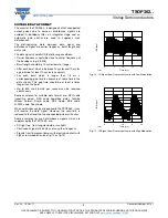
• Signals from fluorescent lamps with electronic ballast with
high or low modulation (see fig. 14 or fig.15)
Fig. 14 - IR Signal from Fluorescent Lamp with Low Modulation
Fig. 15 - IR Signal from Fluorescent Lamp with High Modulation
0
10
15
20
Time (ms)
16920
IR Signal
5
0
10
15
20
Time (ms)
16921
IR Signal
5


