© 2020 Virginia Diodes, Inc.
—All Rights Reserved
7 October 2020
Careful review of the instructions in the “ReadMe” file on the flash memory drive included
with your new PM5B is recommended. It is critical that all instructions are followed for
downloading files onto your computer before connecting the computer and meter via a USB
cable. Call VDI at 434.297.3257 with any questions prior to: connecting the power supply or
a computer to the PM5B, or starting the meter.
1.
Follow installation instructions on the
“ReadMe” file that was provided on the USB memory drive you received with your
new PM5B meter.
2.
If remote operation is desired, be sure to install the VDI-provided software BEFORE proceeding.
3.
With the PM5B Power Switch (rear panel) in the
“OFF” position, connect one end of the sensor cable to the front panel
port of the PM5B readout; connect the other end to the PM5B sensor head.
4.
Connect the AC power cable to the rear panel of the PM5B in its three-prong AC input socket.
5.
Connect the USB cable to the USB port (Type B) on the back panel of the PM5B; connect the opposite end of cable to a
compatible USB port on the computer to be used in conjunction with the PM5B. (Optional)
6.
Turn on the PM5B by flipping the power switch to the
“ON” position: ‘—‘ = “ON”; “O” = “OFF.”
7.
Do not rapidly toggle between
“ON” and “OFF” settings as this will temporarily cause inaccurate meter readings. Maintain
an “ON” or “OFF” setting at least 5 seconds before switching to the opposite setting.
8.
Turn the Range Switch knob on the front panel of the PM5B to a selection appropriate for the power measurement. If you
plan to make a number of measurements across increasingly higher power levels, begin with the lowest level, then
proceed to higher settings.
9.
Allow enough time for PM5B to settle; see PM5B Product Manual for
Settlement Times and Drift,
located in
Section 4
.
10.
See PM5B Product Manual concerning
Use of Tapers in High Frequency Measurements
, located in
Section 5
.
11.
Review conditions affecting
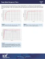
Power Meter Response Times
, located in
Section 6
.
12.
See additional information detailing
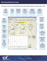
PM5B software,
the
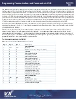
USB
and
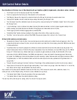
GUI
,
located in
Section 7
.
Modes of Operation: Range Switch Selections
Fixed Range Mode:
Fixed Range Mode can be entered by setting
the Range Switch to 200
μ
W, 2 mW, 20 mW, or 200 mW; the
setting selected reflects maximum measurable power for a given
range. Drift (see Section 4) and Response Time (see Section 6)
should be considered when choosing a range. Fixed Range Mode
can also be controlled via the USB when the Range Switch is set to
“Remote.” When in “Remote” the virtual Range Switch displayed in
the GUI operates as described above. Custom program ranges can also be set by sending the appropriate
command via the USB (see Section 7).
Auto Scaling Mode:
Auto Scaling Mode is entered automatically when the Range Switch is set to “Remote” and can by fully
controlled via the USB (see Section 7). It is generally used to rapidly switch between fixed ranges with much shorter settling times.
This mode of operation has four ranges like Fixed Range Mode; however, in Auto Scaling Mode they become 200
μ
W auto, 2 mW
auto, 20 mW auto, or 200 mW auto. When Range Hold is
“OFF” the instrument automatically adjusts range based upon input
power.
Range Hold:
This feature fixes the range of the instrument and can be turned “ON” or “OFF” when in Auto Scaling Mode in any of
the three upper ranges (2 mW auto, 20 mW auto or 200 mW auto). Turn “ON” by pressing the Zero Button while in an upper range
(2 mW auto, 20 mW auto or 200 mW auto); turn “OFF” by pressing the Zero Button twice within 0.75 seconds. The Range Hold
feature can also be cycled “ON” or “OFF” via the USB by using VDI software (see Section 7), or by sending the appropriate
command via the USB in a custom program.
Range Switch
Select full-scale ranges
from 200 µW to 200
mW. ‘Remote’ enables
USB control and auto
range-scaling; virtual
controls are viewable
on the GUI.
B
Starting and Operating the PM5B
Section
Three


