


© 2019 Virginia Diodes, Inc.
—All Rights Reserved
The PM5 power meter has a USB Type B connector jack at the rear that can be used to interface with the instrument. The USB
interface uses an FTDI chip (Future Technology Devices International). Commands can be sent and received by a computer as a
series of bytes by using FTDI device drivers. The
bytes can be sent using the function “FT_Write” in the device driver FTD2XX.dll,
and the return bytes can be read wit
h “FT_Read”. The Labview library “PM5.llb” includes the programming diagrams that calls
functions in FTD2XX.dll to send and receive data via the USB. Alternately, the USB interface will also be installed as a Virtual COM
port to allow communications with software designed to communicate using COM ports. Also included on the memory stick provided
by VDI are other Labview VIs that use other fu
nctions in FTD2XX.dll not used by the “PM5 Communication.vi” program. See the
“FTD2XX programming guide” on the memory stick for more information about controlling communication via the USB.
Communications to the PM5 that are similar to the PM4 must contain eight byte characters. All messages are prefaced with the
synchronizing character
“!” (0x21) or “?” (0x3f) and terminated with a carriage return (x0d). There is no checksum or other method
of validation within the protocol.
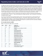
The first, second, third and last bytes are ASCII characters. The first, second and third bytes are the command characters as
shown in Table 1 below. “Set” commands start with the character “!”. In this instance values are written to the PM5. “Query”
commands start with the character
“?”. In this instance the PM5 writes values to the computer. Bytes 4 through 7 are binary. Of
the binary bytes, Byte 4 is the LSB and Byte 7 is the MSB. Bytes 4 through 7 are ignored by most of the commands, except Byte 4
represents rangehold (1-hold, 0-autorange) for the auto scales.
For Communication to the PM5
Table 1:
Command Set for PM5 USB Communications
Byte 1
Byte 2
Byte 3
Command
Set Commands
!
'null'
'null'
No action
!
S
Z
Set Zero (same as pushing zero button)
!
S
C
Calibrate
!
R
1
Set FP Range 200 µW
!
R
2
Set FP Range 2 mW
!
R
3
Set FP Range 20 mW
!
R
4
Set FP Range 200 mW
!
R
5
Set FP Range 200 µW auto
!
R
6
Set FP Range 2 mW auto
!
R
7
Set FP Range 20 mW auto
!
R
8
Set FP Range 200 mW auto
!
C
0
Calibration Heater OFF
!
C
1
Calibration Heater 100 µW
!
C
2
Calibration Heater 1 mW
!
C
3
Calibration Heater 10 mW
!
C
4
Calibration Heater 100 mW
Query Commands
?
'null'
'null'
No action
?
V
C
Query firmware code
?
D
1
Transmit Request one sample
?
D
S
Transmit Stream samples
Programming Communications and Commands via USB
Appendix
One


