background image


BORIS Operating Manual  

Page 7 

8.


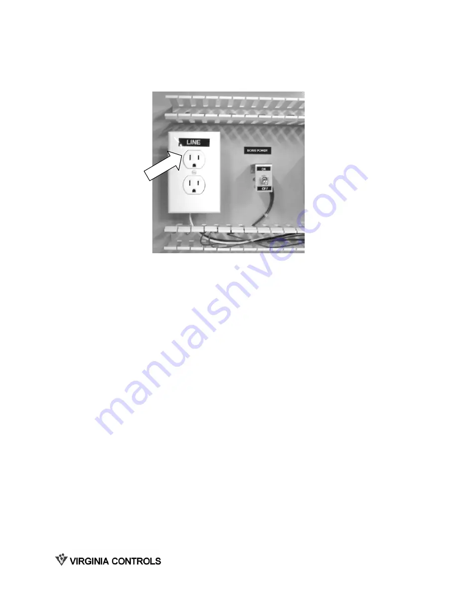
Plug in the connector labeled “LINE” into the outlet box mounted in controller. 

Содержание BORIS 1000VA

Страница 1: ... Controls Inc 2513 Mechanicsville Turnpike Richmond Virginia 23223 Tel 804 225 5530 Fax 804 225 0116 email eng vacontrols com web site www vacontrols com BA T T E R Y OP E R A T E D RE S C U E IN I T I A T I O N SY S T E M 7 5 0 V A 1 0 0 0 V A O P E R A T I N G M A N U A L VIRGINIA CONTROLS ...

Страница 2: ...or Bookmark not defined 4 DISPLAY AND CONTROL FEATURES 9 4 1 Front Panel 9 4 2 Front Panel Pushbuttons 10 4 2 1 On Test 10 4 2 2 Off 10 4 3 Power Meter 10 4 4 Battery Charge Meter 11 4 5 Line Voltage Meter 11 4 6 Front panel Lights 11 4 6 1 AVR Trim 11 4 6 2 On Line 11 4 6 3 AVR Boost 12 4 6 4 Overload 12 4 6 5 On Battery 12 4 6 6 Replace Battery 12 5 BATTERY REPLACEMENT PROCEDURE 13 6 TROUBLESHOO...

Страница 3: ...tion DO NOT mount near open flame or sparks DO NOT install equipment in areas of excessive moisture This equipment has an internal energy source the battery that cannot be de energized by the user The output may be energized when incoming supply power to unit is off Insure disconnect switch OFF before connecting and disconnecting this equipment Use caution when servicing batteries Battery acid can...

Страница 4: ... Controls controller this condition should not occur if batteries were previously charged fully since the controller utilizes the remote shutdown capability of BORIS Special features include surge protection EMI RFI filtering high and low voltage correction without draining batteries as well as automatic battery testing during power up and every 14 days thereafter User replaceable batteries can be...

Страница 5: ...ls B3 B4 is between 110 and 120 VAC 2 Verify that the utility voltage and frequency on BORIS agree with that listed on the schematics and controller label This is normally 120 VAC 60 Hertz 3 Verify that no changes have been made to the plug wiring 4 Check the connection of the 4th pole of the Main Line Disconnect Switch TB 1 L5 should be closed when the disconnect switch is closed and open when th...

Страница 6: ...BORIS in the enclosure and plug the 9 pin D9 connector into the back of BORIS UPS Monitoring Port The connector is already wired to the controller 7 Remove the 3 prong power plug labeled LOAD from the outlet box in the controller and plug it into the back of the BORIS unit ...

Страница 7: ...BORIS Operating Manual Page 7 8 Plug in the connector labeled LINE into the outlet box mounted in controller ...

Страница 8: ...dicator illuminates the load should be reduced before proceeding If the REPLACE BATTERY indicator illuminates recharge overnight and test again If after retesting the indicator remains on replace the batteries CAUTION If the REPLACE BATTERY indicator is illuminated expected on battery run time may not be provided See Section 4 Display and Control Features section for more information 4 To simulate...

Страница 9: ...n when the UPS is supplying utility power to the loads See Section 4 6 2 The AVR Boost LED comes one when the UPS is correcting a low utility voltage condition The loads receive normal power See Section 4 6 3 The Overload LED lights when the loads connected to the UPS exceed the UPS s capacity See Section 4 6 4 The On Battery LED comes on when the UPS is supplying battery power to the loads See Se...

Страница 10: ... battery When pressed this button causes the BORIS on battery audible alarm to be silenced When power returns the alarm is reset so that it will sound during the next power outage This pushbutton has no effect on the low battery audible alarm which sounds when 2 minutes of backup time remain 4 2 2 Off This pushbutton returns the unit to the power up mode which puts BORIS through the self test func...

Страница 11: ... front panel form a bar graph showing the input line voltage Note The UPS will start a self test as part of this procedure The self test does not affect the voltage display This example shows the input line voltage to BORIS is between 114 VAC and 124 VAC 133 VAC 124 VAC 114 VAC 105 VAC 96 VAC 4 6 Front panel Lights 4 6 1 AVR Trim This indicator comes on to indicate that the UPS is compensating for...

Страница 12: ...verity of the overload BORIS circuit breaker may trip 4 6 5 On Battery This light indicates BORIS is running on battery and that the utility voltage building power is not within a safe operating range for the protected load The light will remain on for 4 seconds after the utility power is restored An audible alarm will sound 4 beeps every 30 seconds Press On Test during on battery alarms to stop b...

Страница 13: ...s and open the door 5 Grasp the tab and gently pull the battery out of the UPS 6 Disconnect the battery leads Loosen the connectors by gently wiggling them while pulling straight back from the battery connector 7 Connect the battery leads to the new battery NOTE Small sparks at the battery connectors are normal during battery connection 1 Tilt the front cover forward 2 Unhook the bottom of the fro...

Страница 14: ...positive terminal and the black wire to the negative terminal 9 Dispose of the old battery properly at an appropriate recycling facility or return it to the supplier in the packing material for the new battery See the new battery instructions for more information ...

Страница 15: ... the line BORIS does not provide expected back up time Batteries are weak due to recent utility outage or wear Allow sufficient recharge time normally 8 hours The batteries will wear faster when used often or at higher temperatures All front panel indicators are illuminated and BORIS emits a constant tone Internal fault Do not attempt to use BORIS Return for repair immediately See section 2 4 to r...

Страница 16: ...ll ask you to describe the problem and help solve it over the phone if possible or will give you an RA 6 If the UPS is under warranty normal repairs are covered If not there will be a charge for repair 7 Pack the UPS in its original packaging 8 It is important to pack the UPS properly to avoid damage in transit WARNING Never use Styrofoam beads for packaging Damage sustained in transit is not cove...

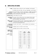
Страница 17: ...ected latching shutdown upon overload Battery And Charger Spill proof maintenance free sealed lead acid battery with 3 to 6 year typical life expectancy typical recharge time is 2 to 5 hours from total discharge state Operating Environment 0 C 40 C 32 F 104 F 0 95 humidity non condensing Dimensions Weight 750VA 6 2 H x 5 4 W x 14 1 D 29 lbs 1000VA 8 5 H x 6 7 W x 17 3 D 41 5 lbs Typical Run Time V...

Отзывы: