6
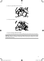
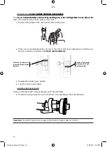
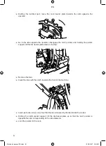
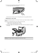
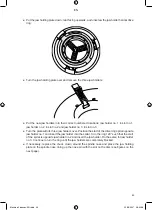
Holding the setting lever, position the scale such that the indication “Remove dies” is opposite
the marker (some force is required):
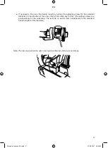
and tighten the locking lever again in order to retain the initial setting of the head.
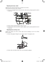
Remove the worn dies and loosen the plate slightly.
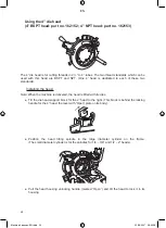
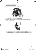
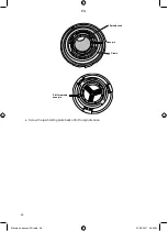
Put the new dies in place, notch facing to the rear, in compliance with the numbering: die no.1
in socket no. 1, die no.2 in socket no.2, etc.
Insert each die until you can feel that the die is blocked by the ball inside the socket.
Note: The line engraved on the die is used to position the die when it is placed in a manually-
opened head. It must not therefore be used as positioning marker with the 2” head.
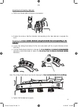
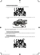
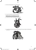
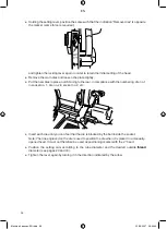
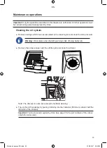
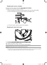
Position the setting cam according to the tube diameter and the desired outside thread
thread
diameter (see pages 29 and 0).
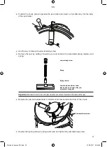
Tighten the lever again by turning it in the direction indicated by the arrow.
●
●
●
●
●
●
Machine 4 pouces-EN.indd 36
22/08/2007 08:59:43
EN
Содержание 162140
Страница 3: ...Machine 4 pouces EN indd 2 22 08 2007 08 59 01 EN ...
Страница 55: ...53 Exploded view of the motor Machine 4 pouces EN indd 53 22 08 2007 09 00 02 EN ...
Страница 57: ...55 Exploded view of the saddle Machine 4 pouces EN indd 55 22 08 2007 09 00 04 EN ...
Страница 59: ...57 Exploded view of the 4 die head Machine 4 pouces EN indd 57 22 08 2007 09 00 05 EN ...
Страница 60: ...58 Exploded view of the automatic opening 2 die head Machine 4 pouces EN indd 58 22 08 2007 09 00 05 EN ...
Страница 61: ...59 Exploded view of the 1 4 3 8 die head Machine 4 pouces EN indd 59 22 08 2007 09 00 07 EN ...
Страница 62: ...60 Exploded view of the tube cutter Machine 4 pouces EN indd 60 22 08 2007 09 00 07 EN ...
Страница 63: ...61 Exploded view of the reamer Machine 4 pouces EN indd 61 22 08 2007 09 00 07 EN ...
Страница 64: ...62 Components of a nipple holder Machine 4 pouces EN indd 62 22 08 2007 09 00 08 EN ...
Страница 65: ...EN ...
Страница 66: ...EN ...
Страница 67: ...EN ...

