background image

FILLING THE SOLUTION TANK

1.

The FANG32T can only be filled in the rear 
of the machine.  There is a fill cap that can be 
removed so the tank can be filled with a hose. 

2.

Fill the solution tank with up to 30 gallons of 
water. (water temperature should not exceed 
140 degrees F) 

3.

The clear tube under the fill port has gallon 
markers to help determine the water level in 
the solution tank. 

:

 Do not put any flammable materials 

into solution tank. This can cause an explosion 
or a fire. Only use recommended cleaning 
chemicals. Contact your Viper distributor for 
recommended chemicals. 

MACHINE OPERATION 

: Do not operate machine unless you 

have read and understand this manual. 

1.

Before the machine will operate, the key 
switch must be turned into the "on" position.  
The key is located on the left side of the 
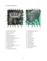
control housing. (see machine components, 
item #19) 

2.

Set control housing to a comfortable operating 
height by squeezing together the tow thumb 
levers directly underneath the housing (see 
machine components item #16) 

3. Lower squeegee assembly to the floor.  There is 

a squeegee lift handle located on the back left 
of the machine, just under the control housing. 
(see machine components, item #14) Slightly 
lift up on the handle and move it to the right, 
the squeegee is now ready to be lowered to the 
floor.

4.

Lower the brush head to the floor by pushing 
the brush lower button on the control housing. 
(see machine components, item #7) 

5.

Turn vacuum motor switch to "on" position. 
(see machine components, item #1) 

6.

Turn the brush motor switch to "on" position. 
(see machine components, item #2) 

a. Brushes will not spin until the operating 

triggers are pulled. 

7. Turn the solution switch to "on" position. (see 

machine components, item #3) 

a. Solution will not begin to flow until the 

operating triggers are pulled. 

8.

To begin scrubbing, pull on one or both of the 
red operating triggers. (see machine 
components, item #27)  When the triggers are 
pulled, the brushes will begin to spin, the 
solution will begin to flow, and the machine 
will propel itself. 

9.

This machine is self-propelled. The speed can 
be adjusted by a dial located on the right side 
of the control housing. (see machine 
components, item #9) 

10. This machine has reverse. In order to activate 

reverse, there is a toggle switch on the left 
side of the control housing. (see machine 
components, item #20)  The toggle switch 
must be pulled / pressed to activate reverse 
motion.

: Do not keep the machine in the same 

position with the pad / brush spinning, or you 
could cause damage to the floor. 

11. Adjust the amount of solution flow by turning 

the solution control knob. Turn the knob to 
the right for more solution, or turn left for less 
solution. (see machine components, item #8) 

12. There is an hour meter located on the top of 

the control housing. (see machine components, 
item #4) The operator can see the operation 
time. 

6

Содержание Fang 32T

Страница 1: ...REV 02 09 12...

Страница 2: ...are entitled to the best protection by one of the most comprehensive warranties in the industry Thank you for purchasing Viper products Tom VanderBie CEO TABLE OF CONTENTS SAFETY PRECAUTIONS 3 MACHIN...

Страница 3: ...ine prior to operating it 4 BEFORE LEAVING OR SERVICING MACHINE x Stop machine on level ground x Turn machine off 5 WHEN SERVICING MACHINE x Read operators manual thoroughly prior to operating or serv...

Страница 4: ...4...

Страница 5: ...onnections to prevent battery corrosion DO NOT DROP THE BATTERIES INTO COMPARTMENT MACHINE SET UP PRE OPERATION CHECKS 1 Sweep or dust mop the surface to be cleaned 2 Check battery meter to make sure...

Страница 6: ...h head to the floor by pushing the brush lower button on the control housing see machine components item 7 5 Turn vacuum motor switch to on position see machine components item 1 6 Turn the brush moto...

Страница 7: ...rotect them from damage If a breaker trips it can t be reset immediately You must first determine what caused the breaker to trip and allow the motor to cool down before you can reset the breaker The...

Страница 8: ...d an explosion or fire can result Keep sparks and fire away from batteries at all times When charging the machine make sure the battery compartment is left open 1 Place charger and machine in a well v...

Страница 9: ...d lose fasteners 2 Lubricate all grease points and pivot points with silicon spray and approved grease 3 Place machine over a floor drain Flush solution system by pouring 3 gallons of hot water and ap...

Страница 10: ...store the machine indoors 2 Always store the machine in a dry area 3 Always store the machine with pads brushes removed 4 Always store the machine with the squeegee assembly in up position 5 If stori...

Страница 11: ...ve filter and clean Solution line obstructed Remove solution line and clean Solution flow adjustment knob in need of adjustment Increase flow by twisting solution adjustment knob to the right Decrease...

Страница 12: ...12...

Страница 13: ...DC 1 5 VF13503 NUT LOCK M8 1 6 VF84112 PLATE TRANSAXLE 2 7 VF13517 WASHER PLAIN M10 X M26 X 2 14 8 VF13504 NUT LOCK M10 12 9 VF84122 CHAIN STATIC 1 10 VF13535 WASHER PLAIN M8 X M20 X 2 1 11 VF14235 SC...

Страница 14: ...14...

Страница 15: ...X 2 2 7 VF84116 BUSHING 2 8 VF13535 WASHER PLAIN M8 X M20 X 2 7 9 VF13519 WASHER LOCK M8 7 10 VV13604 SCREW M8 X 20 7 11 VF84336 BRACKET BRUSH LIFT 1 12 VF84332 ACTUATOR 36VDC 1 13 VF84310 BRACKET AC...

Страница 16: ...16...

Страница 17: ...19 VF82123 DECAL 1 20 VF84135 WIRE 4 X 600 RED 1 21 VF84148 WIRE 4 X 600 BLACK 1 22 VF14232 SCREW M6 X 10 2 23 VV13607 WASHER LOCK M6 8 24 GT13032 WASHER PLAIN M6 X M16 X 1 5 8 25 VF84109 BRACKET 1 2...

Страница 18: ...18...

Страница 19: ...AMP 2 2 15 VF84124 DECAL BATTERY INSTALLATION 1 16 VF14235 SCREW M8 X 35 1 17 VF13535 WASHER PLAIN M8 X M20 X 2 2 18 VF84107 BRACKET DROP ARM 1 19 VF84133 BUSHING 1 20 VF84216 BUSHING 1 21 VA13491 SCR...

Страница 20: ...20...

Страница 21: ...46 TUBING 11 5mm ID 275mm 1 19 VF84303 BRACKET LIFT LEFT 1 20 VV20509 SCREW M5 X 10 4 21 VF84325 DOOR SCRUB HEAD 2 22 VF82042 ELBOW 2 23 VF82148 CLAMP 16mm 6 24 VF82138 TUBING 11 5mm ID 75mm 1 25 VF84...

Страница 22: ...W SELF TAPPING 1 4 1 6 49 VF83118 SPACER 2 50 VF83132 SPRING 2 51 VF83131 CLAMP BRUSH PLATE 2 52 VF13502 NUT LOCK M6 6 53 VF83133 STUD 6 54 VF14225A SCREW M6 X 40 6 55 VF84134 PUSH SCREW 7 56 VF82013...

Страница 23: ...23...

Страница 24: ...EE BLADE SQUEEGEE FRONT PU FANG 32T SQUEEGEE SUPPORT KNOB M8 WASHER PLAIN M8 X M16 5 X 1 5 BUSHING HANDLE LIFT FRONT SQUEEGEE SUPPORT SCREW M12 X 130 BACK SQUEEGEE SUPPORT ARM SQUEEGEE LIFT PIN M2 X 2...

Страница 25: ...25...

Страница 26: ...L VALVE 15mm DN NPT 1 2 1 17 VF82168 3 SEAT FILTER 1 18 VF82168 4 SCREEN 80SS FILTER 1 19 VF82168 5 GASKET FILTER 1 20 VF82168 2 COVER FILTER 1 21 VF82168 FILTER ASSY 1 22 VF84347 TUBING 17 5mm ID 185...

Страница 27: ...27...

Страница 28: ...LABEL SPEED CONTROL 1 25 VF84710 PIN HANDLE LOCK 2 26 VF81716 SPRING 1 27 VF81710 PIN HANDLE ADJUSTMENT 2 28 VF81729 POTIENTIOMETER 4 7K 1 29 VF84718 PLATE 1 30 VF84719 BOARD SPEED CONTROL 1 31 VF8471...

Страница 29: ...G BLK 15 14AWG RED 01 14AWG BLK 13 14AWG RED 10 10 12 20 0 3 MAIN SOLENOID SOLUTION SOLENOID ACTUATOR MOTOR LEFT BRUSH MOTOR RIGHT BRUSH MOTOR VACUUM MOTOR DRIVE MOTOR _ 03 12AWG BLK 5 16AWG WHT 0 16A...

Отзывы: