


16
Balancing the head
10
Balancing the Vision 11 head achieves two objectives. Firstly, when a head is correctly balanced the
operator will need a minimum amount of even effort to move the head. Secondly, once balanced, the head
and its payload can be set to any tilt position and the head will maintain this position with “hands off”.
11
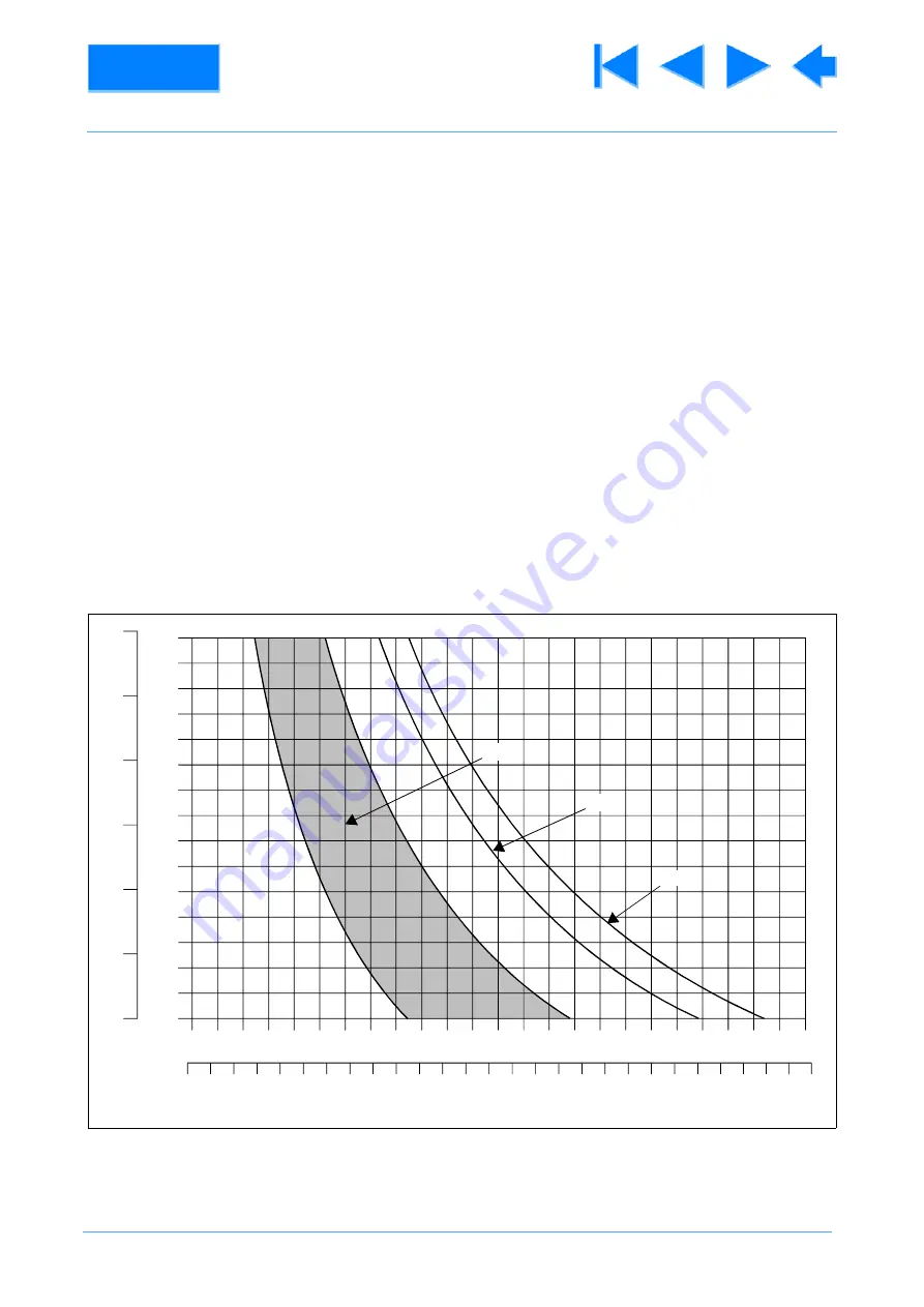
The graph
illustrates the relationship between load and centre-of-gravity (C of G) height and
may be used to ascertain the suitability of the head for any given combination of camera, lens and
accessories. The shaded area of the graph corresponds to those loads/C of G heights that can be balanced
over the full tilt range. The areas to the right indicate the progressively reducing tilt range over which the head
can balance higher loads.
12
Prior to balancing the head ensure that the pan bars and any ancillary equipment have been fitted in
order to prevent upsetting the balance once it has been achieved.
12.1 Release the tilt brake
. Turn the balance knob
counter-clockwise until the head falls away
from horizontal under the weight of the camera.
and slide the camera backwards or forward until it balances
horizontally. Apply the slide clamp
12.3 Turn the balance knob
clockwise until the camera does not fall away when the head is tilted
and released.
Fig 2.2 Balance Graph
C
of G
HE
IGHT
TOTAL LOAD
90
100
130
2
3
4
5
6
7
8
110
120
140
150
160
170
180
190
200
80
70
60
4
6
8
24
12
14
16
18
kg
20
22
8
12
16
20
24
28
32
36
40
lb
44
48
2
4
50
±90°
±60°
±40°
10
26
52
56


