3
The separator device is an accessory used in 2-WIRE ELVOX systems to create separate communications islands and it is used together with the type 6922
power supply. It should be used in the following cases:
- In building complex type installations where there is one or more main entrance panels, one or more buildings with ’one or more secondary panels inside.
One separator for each building.
- In installations where panels are connected to an interphone or to a video entry system outside. One separator for each panel outside.
- In installations where interphones and video entry systems are connected, that should not engage the lines of the other devices while speaking.
Terminals and jumpers
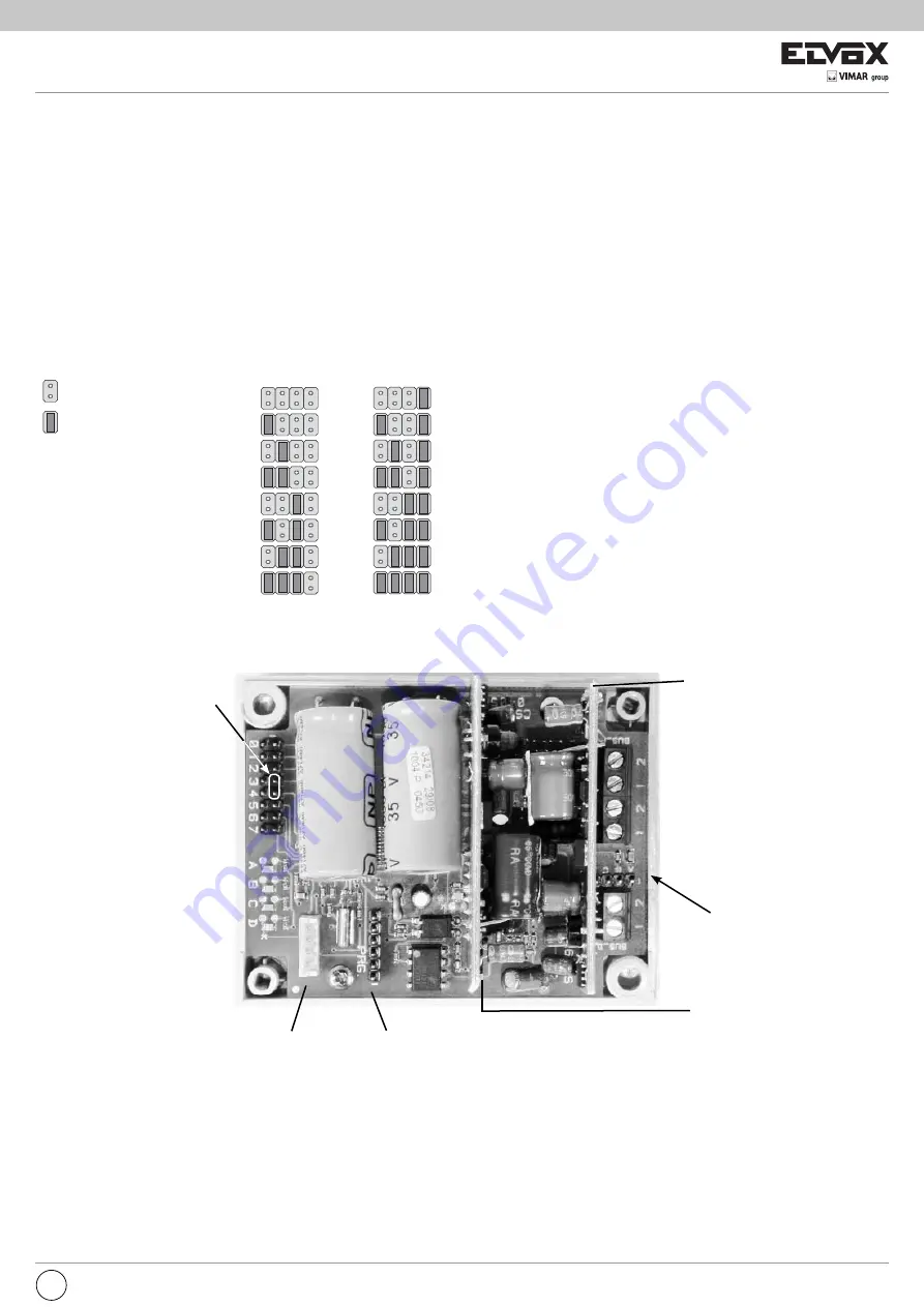
1, 2 (BUS_P)
Main bus line, to the main panel or branch of the installation.
1, 2 (BUS_D)
Secondary bus line, to the interphones/video entry systems or isolated branch of the installation.
A, B, C, D
Establishing video signal
0, 1, 2, 3
ID programming.
It is possible to connect up to a maximum of 16 separators in the same installation. It is necessary to associate an ID code different to them by using the 0,
1, 2, 3 jumpers.
IDENTIFICATION
Jumper not inserted
Jumper inserted
LED 1 on
means the secondary bus is powered.
LED 2 on
means the main bus is powered.
TXD (LED A) and RXD (LED C)
communication underway on main bus
TXP (LED B) and RXP (LED D)
communication underway on secondary bus
Note:
- If no calls have been made or no services enabled (open lock, enablers, etc.) in the installation, the TXD, RXD, TXP, RXP LEDs should remain off.
- In the event that, within a system, riser separators need to be exchanged or a used separator must be utilised, it is necessary to reset the system. This is
done by short-circuiting the pins labelled 3 and 4 which are used to assign the ID code, on the interior side of the board (see Fig. 1). The reset is confirmed
by the LEDs which will flash rapidly in the sequence D-C-B-A.
Indicators
In the separator there are two pairs of LED lights in the horizontal card, and one LED for each card in the vertical cards.
Fig. 1
LED 1
LED 2
TXD
TXP
RXD
RXP
4, 5, 6, 7 = Jumper not used
[
0, 1, 2, 3 = ID programming
[
Serial
PRG.
(Reserved)
ABCD
Reset
0 1 2 3
ID
0
1
2
3
4
5
6
7
0 1 2 3
ID
8
9
10
11
12
13
14
15
EN


