4
EN
R
L1
5 6 7 8
15
P1
PRI
0
2
3 P2
S1
P2
CH
B
D
C
E
A
1
6
3
4/5
A
SR
SD
C
1
5
6
4
2
3
CN4
3
F
F
7
6
5
8
3
4
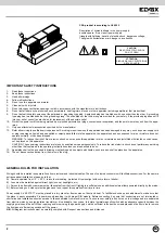
WIRING DIAGRAM FOR 2-WIRE (1+n) DOOR ENTRY SYSTEM WITH CONVERSATION PRIVACY
Phone
Art. 0900/837
* Art. 0900/137
Art. 8873
* Art. 8877
POWER SUPPLY
Art. 6837/C17
Mains
Conductors
up to 200 m.
up to 50 m.
up to 100 m. .
*
N.B.
: This installation may be carried out also with interphones Art.0875/037, (8877) and/or Art.0900/137 without conversation pri vacy.
Conductor section
DIAGRAM N° C1975
To enable the conversation privacy on interphone Art. 6201 desconnect the “ A ” jumper and connect the Art. 7155 card.
0 - 15 - 3 - 5 - 8 - S1
0,5 mm2
0,75 mm2
1,5 mm2
others
0,25 mm2
0,5 mm2
1 mm2
A
- Entrance panel with speech unit
Series 1300, 1200, 3300, 8000, 8100, PATAVIUM
B
- Additional push-button for lock
C
- Serratura elettrica 12V ~
D
- Speech unit
Art. 0930/000.04, 930A
E
- Diode strip
Art. 0027/005 - 0002/994.05
Phone
Art. 6201
Art. 6201 + 7155


