Viking ESFR Скачать руководство пользователя страница 11

11 

3.2  Hydraulic Calculation Procedure: 


1.  A calculation with a design of twelve ESFR K25.2 VK510 Sprinklers and water, 

using four sprinklers on three most remote lines, discharging at the minimum 
design pressure for the hazard, with piping friction loss determined by Hazen- 
Williams method of determining friction loss in piping. 

 
2.  A second hydraulic calculation with a design of six K25.2 ESFR sprinklers 

using propylene glycol and the physical properties at the discharge 
temperatures, using four sprinklers on the most remote line and two sprinklers 
on the second most remote line, discharging at a minimum design pressure for 
the hazard, with piping friction loss determined by the Darcy-Weisbach method 
of determining friction loss in piping. 

 
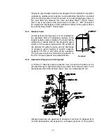
3. The 1,100 gallon (4,163 liter) volume restriction for tree type piping 

configuration is for the piping included in the remote area (12 sprinklers) and 
the supply main piping back to the base of the sprinkler riser above the primary 
Easy Riser

TM

 Check Valve clapper. 

 
4.  Additional mains and sprinkler lines attached to the system, but not in the direct 

path to the sprinkler riser base, need not be considered for the system volume 
limitation if acceptable by the Authority Having Jurisdiction. 


4.0 

PRE-PRIMED SINGLE INTERLOCKED PREACTION SYSTEM FOR COLD 
STORAGE 

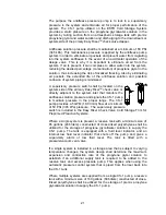
The Viking “Pre-Primed Single Interlocked Preaction” Cold Storage System is electrically 
operated using a listed releasing control panel, listed detection system as described in 
the technical data, and a listed Viking single interlocked preaction assembly, two Viking 
Easy Riser

TM

 Check Valves. The first or primary Easy Riser

TM

 Check Valve and trim 

includes connections for antifreeze supply from the Viking Model CS-1 pump control 
assembly that also includes a reservoir for antifreeze and controls. A pressure switch to 
control the supervisory antifreeze pressure is also included. The antifreeze must fill the 
system less any air pockets in order to prevent water from entering cold storage area 
and contaminating the antifreeze mixture, which could cause freezing. A Viking 
automatic air vent assembly (Model AV-1) is recommended for installation at the end of 
all branch lines and high points of the supply mains. A second Easy Riser

TM

 Check 

Valve that includes a system main drain and a by-pass line is installed approximately 5 
to 10 ft (1,5 to 3,0 m) above or downstream of the first check valve between the freezer 
wall and the primary check valve. This valve is required to protect the riser assembly and 
clapper of the first check valve from freezing due to hydrodynamic thermal transfer of 
cold antifreeze from the freezer to the riser check valve. The by-pass line is required to 
allow all system controls on the primary check valve to function properly. This valve also 
helps to minimize insulation and heat trace requirements to the riser system outside of 
the freezer. 
 

• 

The single interlocked preaction control valve assembly is a standard Viking 
Model E-1 or F-1 Deluge Valve including Conventional Deluge Trim with Electric 
Release. This valve controls the supply water to the system having a static 
supply pressure capable of supplying adequate starting pressure of the most 

Содержание ESFR

Страница 1: ...INGLE INTERLOCKED PREACTION COLD STORAGE SYSTEM MANUAL The Viking Corporation 210 N Industrial Park Road Hastings MI 49058 Telephone 269 945 9501 Technical Services 877 384 5464 Fax 269 945 9599 Decem...

Страница 2: ...14 5 1 1 1 General Piping and Material Recommendation 15 5 1 2 Primary Check Valve Main Drain 16 5 1 3 Reclaim Tank 17 5 1 4 Automatic Pressure Control System 17 5 1 5 Solution Test Valves 18 5 1 6 R...

Страница 3: ...36 7 4 2 Handling 36 7 4 3 Location 36 7 4 4 Piping and Connections 36 7 5 Electrical Connections 37 7 6 Start up 38 8 0 Pressure Switch 38 8 1 System Control Switch 38 8 2 Wiring Diagram 39 8 3 Press...

Страница 4: ...Fill Procedure 47 15 1 Filling the Reservoir Tank 47 15 1 1 Gravity Fill 47 15 1 2 Pump Assist Fill 47 15 2 Filling Systems 48 16 0 System Solution Test and Maintenance 49 16 1 Testing the Solution 4...

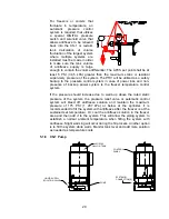
Страница 5: ...5 Figure 1 Straight Through Configuration...

Страница 6: ...6 Figure 2 Angle Style Configuration...

Страница 7: ...ssure Upon operation of the sprinkler s the pressurized propylene glycol water solution is distributed from the sprinkler Water from the supply system pushes out the propylene glycol water solution at...

Страница 8: ...m run of pipe For systems in unheated areas subject to freezing branch lines shall be pitched at per 10 ft 4 mm m and mains at per 10 ft 2 mm m run of pipe This system shall be designed by qualified f...

Страница 9: ...m with ceiling height up to 45 ft 3 in 13 8 m with a minimum system design pressure of 60 PSI 414 kPa 3 0 SYSTEM DESIGN 3 1 Hydraulic Calculations At 21 F 29 4 C the 50 solution of propylene glycol w...

Страница 10: ...10...

Страница 11: ...ata and a listed Viking single interlocked preaction assembly two Viking Easy RiserTM Check Valves The first or primary Easy RiserTM Check Valve and trim includes connections for antifreeze supply fro...

Страница 12: ...antifreeze from the freezer and protect the primary check valve from freezing near the atmospheric air surface of the clapper and seat This valve includes a main drain and a special 3 8 I D copper tub...

Страница 13: ...nts apply to installation of the Viking ESFR Cold Storage System with the following exceptions Commodity limited to Class II or less limited to wood pallets Maximum ceiling height to bottom of inside...

Страница 14: ...ncluding test pressures of pumps at zero flow Detection System shall be capable of operation prior to or equal to an ESFR Sprinkler having an RTI Response Time Index of 50 or less No linear detection...

Страница 15: ...ater solution in the system Additional vent or bleed valves shall be installed on the end of each branch line at high points and feed mains at high points to ensure air is vented from the system This...

Страница 16: ...e glycol solution A re claim tank with adequate capacity of the largest system s shall be located near the system riser s System drain piping shall be arranged to discharge to the re claim tank 5 1 2...

Страница 17: ...of the largest system volume installed The tank shall be utilized as a reclaim tank for the propylene glycol solution in the system piping when the system s are drained for system service and for dis...

Страница 18: ...ary Easy RiserTM check valve The most remote location from the Easy RiserTM check valve One valve located at the end of 50 of the line piping directly on the Model AV 1 Air Vent Valve assembly A test...

Страница 19: ...ation of the system might occur due to temperature fluctuation is in a warm up mode of the freezer which is very rare once it is put into service Also variation in system pressure due to temperature d...

Страница 20: ...backup power system to the freezer temperature control system If the pressure should increase due to warm up above the rated static pressure of the system the pressure relief valve or automatic contr...

Страница 21: ...jacent to the system inlet that monitors the antifreeze solution pressure and signals the CS 1 pump to maintain pressure in the proper range The CS 1 pump provides a 5 GPM 18 9 l min flow at a minimum...

Страница 22: ...that is certified by the manufacturer or a third party agency is to be installed in the system piping Field mixing of propylene glycol and site water is strictly prohibited as the control of the mixtu...

Страница 23: ...m side is required in order to provide a low pressure alarm in the case of antifreeze pressure loss due to sprinkler operation without a fire condition In this case the antifreeze supply must be manua...

Страница 24: ...nance solution supply tank The CS 1 pump will stop running when the pressure in the section of piping is 50 PSI 344 kPa minimum or the set pressure of the system pressure switch Ensure there is no tra...

Страница 25: ...fill pump NOT the CS 1 pump to the connection located on the main drain assembly 3 Close the main drain valve vent bleed valves and low point drains if opened Ensure there are no openings on system p...

Страница 26: ...to close at a pressure below the PRV set point and open above the shut off pressure of the sprinkler system control switch of the pump system A normally closed solenoid valve is to be installed on the...

Страница 27: ...supply required is 115 volt 50 or 60 hz with 15 20 amp GFI protected circuit The solenoid valve is wired directly through the system pressure switch and system alarm pressure switch as described belo...

Страница 28: ...previously set value Depress the Set button and hold until the value changes 5 seconds Set the value to 0 10 Depress the Mode Enter button to return to dr1 11 Depress the Mode Enter button several ti...

Страница 29: ...r should only be used if there is a value in COF 6 5 DAP should always be set at 0 to ensure that the system shuts down the solenoid as soon as the pressure is obtained DiS should be set at d1 d2 or d...

Страница 30: ...uipment is designed to be safe in the use for which it was planned provided it is installed started up operated and maintained in accordance with the instructions in this manual Therefore all personne...

Страница 31: ...the fill process The CS 1 pump is to be utilized to bring the solution to maintenance pressure normally 50 PSI 344 kPa pressure at the primary check valve and is designed to maintain system pressure...

Страница 32: ...the pump will turn on until the pressure at the CS 1 rises above a set level In Automatic mode pump operation is inhibited if the level of liquid in the unit s storage tank drops below the level swit...

Страница 33: ...Input 5 System 1 Inputs Input 6 System 2 Inputs Input 7 System 3 Inputs Input 8 System 4 Inputs Input 9 System 5 Inputs Input 10 System 6 Inputs Input 11 Switch A Down Position Input 12 Switch A Up Po...

Страница 34: ...tput 8 SYSTEM 6 SOLENOID VALVE Output 8 on when Manual Mode Input 1 on and Input 10 on and Input 11 on and Input 13 on OR Automatic Mode Input 2 on and Input 10 on Output 9 LEVEL SWITCH RELAY COIL Out...

Страница 35: ...35...

Страница 36: ...MBIENT CONDITIONS OR EXTREME DUST AND DIRT Install the CS 1 indoors in a clean dry non corrosive environment This equipment is not to be installed outdoors exposed to the weather Position the CS 1 in...

Страница 37: ...red and threaded to a proper depth and length before installation Threads should be inspected for cleanliness and depth of cut Good quality pipe compound should be used to ensure a good leak tight fit...

Страница 38: ...pancies before operating the unit 1 The unit is bolted to a firm level surface 2 Area temperature will always remain between 40 F and 100 F 4 and C 3 Dielectric unions if needed are installed between...

Страница 39: ...parameter value Display mode the Set button is pressed until the display of the parameter value is changed Internally the unit remains in the operating mode It continues its monitoring function with...

Страница 40: ...s the Mode Enter button and the value SP1 appears 17 Depress the Set button The value that appears is the factory or previously set value Depress the Set button and hold until the value changes 5 seco...

Страница 41: ...t Do not over tighten a Mount the Alarm Pressure Switch in the upright position threaded connection down 3 To wire the unit proceed as follows a De energize electrical circuits involved b Use the spec...

Страница 42: ...chanical properties per ISO 898 1 Class 8 8 Hex nuts and bolts are zinc electroplated followed by a yellow chromate dip Gaskets Grade E EPDM NSF 61 Certified 30 F to 230 F Service Temperature Range 40...

Страница 43: ...tion during temperature cycles The lubricant on the interior of the gasket will act to improve the chemical resistance of the gasket material by providing a thin lubricant barrier between the piping s...

Страница 44: ...th conventional and electric release trims The riser consists of two Viking Easy RiserTM Swing Check Valves one with special cold trim and the second with by pass trim to isolate the antifreeze in the...

Страница 45: ...r use in applications having a minimum temperature as low as 8 F 13 3 C The piping system is filled with pressurized propylene glycol and water solution maintained from a pressure pump system that con...

Страница 46: ...rculation allows the riser pipe to maintain a very cold temperature as supplied from the freezer area The moisture in the heated area air will cause formation of liquid on the pipe surface Due to the...

Страница 47: ...pen the shut off valve on the supply container and supply isolation valve on the CS 1 5 Open the pump suction isolation valve and allow liquid to enter the reservoir tank If there is enough liquid in...

Страница 48: ...p seals and possibly damage the pump impeller Follow the steps below 1 Turn off and isolate the electrical supply to the unit 2 Close the Supply Isolation and Tank Fill valves 3 If not already connect...

Страница 49: ...ection for supply and maintenance of the antifreeze solution to the system above the check valve A suitable portable pump can be utilized to fill the system to the static water pressure The CS 1 pump...

Страница 50: ...be drained Five percent 5 of the pendent ESFR sprinklers in all locations throughout the system are to be removed and inspected for frozen solution If any of the pendent ESFR sprinklers are found wit...

Страница 51: ...1 pressure switch setting 1 Verify system pressure switch setting is correct The CS 1 pressure switch setting must not be adjusted higher Adjust CS 1 switch setting lower if approved byfactory Failure...

Страница 52: ...Easy Riser Bypass Trim 14038 14039 14040 07921 Premixed Propylene Glycol Solution Firefighter Eliminator F 21 F 29 4 C 55 Gallon 208 2 liter Drum 12967 55 275 Gallon 946 3 liter Drum 12967 275 13050 1...

Страница 53: ...adjusted 1 13057 Pressure Switch Cable 1 13231 Magnetic Starter 1 13058 Overload Heater Indicate Unit Voltage for Correct Selection 208V 60 HZ 3 PH 13059 230V 60 HZ 3 PH 13060 460V 60 HZ 3 PH 13061 5...

Отзывы: