manualshive.com logo in svg
background image

11

8.  Assemble grille brackets to 72” grille using the 16 screws removed in step 2c.
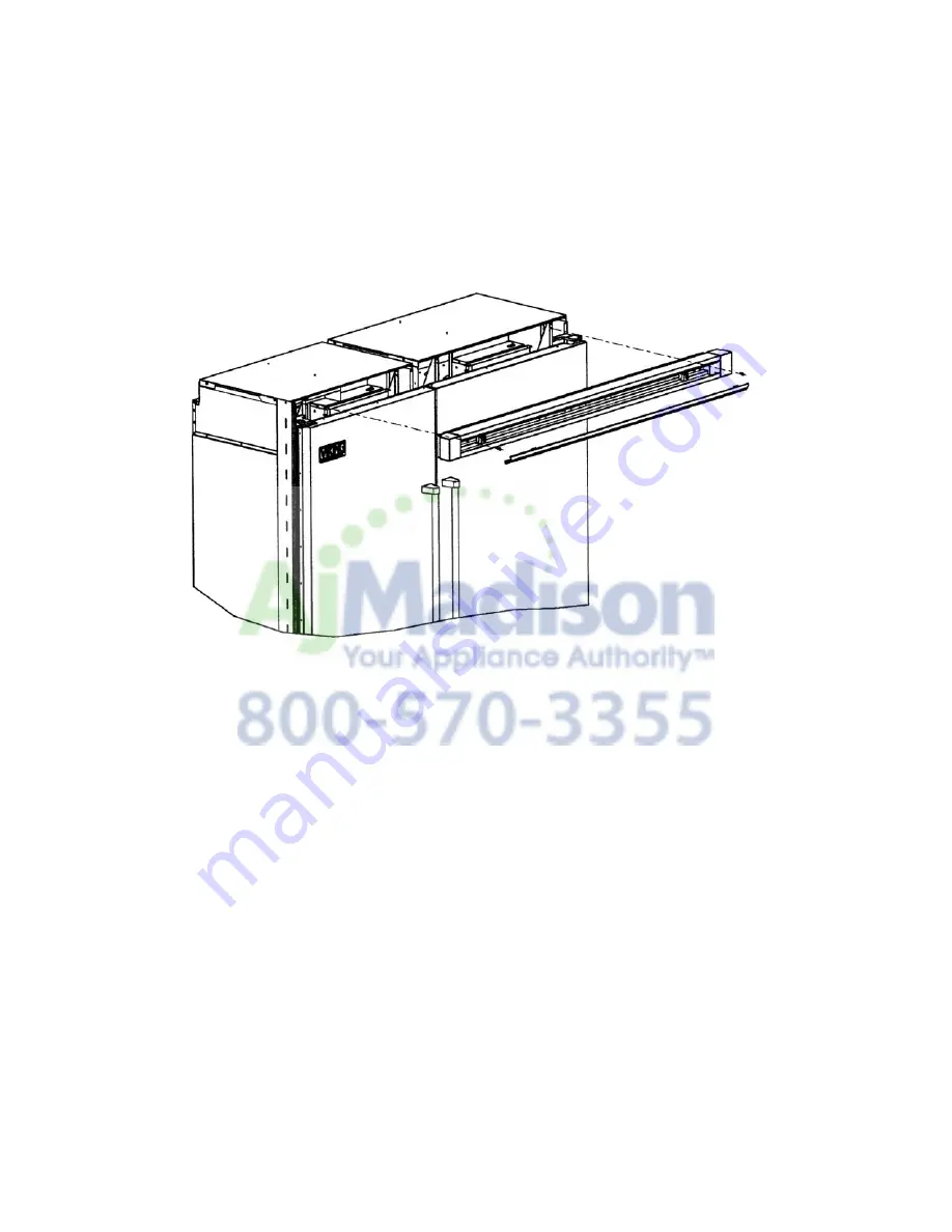
9.  Remove 72” center grille blade by lifting up and pulling forward.  

10.  Insert 72” grille into refrigerators.  Screw 72” grille assembly into units with (4) screws removed in step 2b.

Содержание BRTGK72SS

Страница 1: ...s may be required BRTGK72SS Qty 12 PBRTGK72SS Qty 12 2 saddle valves do not use self piercing valves assure that floor will support refrigerator door panels and contents approximately 1200 lbs 540 kg provide a properly grounded electrical outlet assure that location will permit appliance doors to open 90o minimum Most of the refrigerator s weight is at the top Extra care is needed when moving the ...

Страница 2: ...71 1 2 181 6 cm Cutout Height Min 82 7 8 210 3 cm Max 84 1 16 213 5 cm Cutout Depth 24 61 0 cm min Electrical Requirements 2 115 volt 60 Hz 15 amp dedicated circuit 3 wire cord with grounded 3 prong plug attached to product Maximum Amp Usage 9 9 amps per unit Inlet Water Requirements 2 1 4 copper tubing inlet waterline minimum 20 psi maximum 120 psi Overall Interior Capacity per unit Refrigerator ...

Страница 3: ...TRICAL RECEPTACLE LOCATIONS SHADED AREAS 1 2 5 cm TYP FOUR 2 per unit 82 7 8 210 5 cm Min anti tip board and opening height 84 1 16 213 5 cm Max anti tip board and opening height 71 1 2 181 6 cm FOR TWO PROFESSIONAL STYLE 36 W BOTTOM MOUNT REFRIGERATORS 35 13 16 91 5 cm 39 3 16 99 5 cm Water line entry area Water line Water line ...

Страница 4: ...it must be firmly s seated under anti tip board 6 15 2 cm 6 15 2 cm 9 22 2 cm Electrical outlet location Electrical outlet location Water line entry area 82 7 8 210 5 cm min anti tip board and opening height 84 1 16 213 5 cm max anti tip board and d opening height 73 3 8 186 4 cm SITE PREPARATIONS AND CONSIDERATIONS PBRTGK72SS PROFESSIONAL 36 W BOTTOM MOUNT DUAL INSTALLATION CABINET OPENING DIMENS...

Страница 5: ...and pulling forward b Remove the grille end cap assembly by removing the four 4 screws in each black air duct c Remove the black air ducts by removing the eight 8 screws on the right hinge model and the seven 7 screws on the left hinge model Save the air ducts for the 72 grille installation GRILLE ASSEMBLY INSTALLATION PROFESSIONAL MODEL BRTGK72SS FOR PBRTGK72SS INSTALLATION SKIP TO PAGE 9 SCREW H...

Страница 6: ... shim included in the full length grille kit Left Hand Cabinet Side Trim Power Switch Showroom Switch 3 Verify operation by plugging in power cord Power switch will be shipped in the ON position and showroom switch will be in the ON position If showroom switch is switched to the OFF position showroom mode is engaged and power is shut off to the compressor This mode is for showroom display only ...

Страница 7: ...hat is to be installed on the left side of the installation Replace this side trim with the connection J shaped side trim and shim included in the full length grille kit 6 Place 1 2 5 cm spacer material on either left or right hand unit as shown on next page The spacer material should be located off the bottom of the unit and should not extend the entire height of the unit 7 Engage the right hand ...

Страница 8: ...LES 16 Holes 15 Screws 8 Assemble air ducts to 72 grille using the supplied 15 screws removed in step 2c 9 Remove 72 center grille blade by lifting up and pulling forward 10 Insert air ducts and 72 grille into refrigerators Screw air ducts into units with four screws per unit ...

Страница 9: ...le blade by lifting up and pulling forward b Remove the grille end cap assembly by removing two 2 screws c Remove grille brackets by removing four 4 screws in each grille assembly REAR VIEW OF GRILLE ASSEMBLY TOP VIEW OF GRILLE ASSEMBLY 72 182 9 cm 30 1 32 76 3 cm 3 3 8 8 6 cm 4 7 32 10 7 cm 30 7 8 78 4 cm Power Switch Showroom Switch 3 Verify operation by plugging in power cord Power switch will ...

Страница 10: ... length grille kit 6 Place 1 2 5 cm spacer material on either left or right hand unit as shown on next page The spacer material should be located off the bottom of the unit and should not extend the entire height of the unit 7 Engage the right hand unit s left side trim into the J shaped portion of the left side unit s right side trim Cabinet Side Trim Z Shape Cabinet Cabinet Right Hand Door Unit ...

Страница 11: ...ts to 72 grille using the 16 screws removed in step 2c 9 Remove 72 center grille blade by lifting up and pulling forward 10 Insert 72 grille into refrigerators Screw 72 grille assembly into units with 4 screws removed in step 2b ...

Страница 12: ...Viking Range Corporation 111 Front Street Greenwood Mississippi 38930 USA 662 455 1200 Specifications subject to change without notice http www vikingrange com F20083B PS0306VR ...

Отзывы: