Document: LT0109
Vigilant MICROVAC Owner's Manual
Installation, Wiring, Setup, and Commissioning
Issue 1.31
5 April 2000
Page 2-5
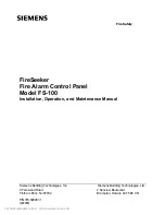
MICROVAC
BGA
+O
─────────────────────────────────
O
─────────────
O
─────────┐
25
│
N/O
│
┌┴┐
BGA Input / BGA /
│
│1
5k EOL
24
│
CONTACTs
│
└┬┘
-O
─────────────────────────────────
O
─────────────
O
─────────┘
Short Circuit Fault Monitoring not used. (Switch 2:2 ON)
MICROVAC
BGA
+O
─────────────────────────────────
O
─────────────
O
─────────┐
25
│
N/O
│
│
/ BGA /
│
BGA Input
│
CONTACTs
│
┌┴┐
┌┴┐
┌┴┐
│
│
1
5k EOL
│
│1
5k
│
│1
5k
└┬┘
24
└┬┘
└┬┘
│
-O
─────────────────────────────────
O
─────────────
O
─────────┘
Short Circuit Fault Monitoring used. (Switch 2:2 OFF)
FIG 2.5
BGA INPUT WIRING
Note: FIP and BGA contacts should close to operate the alarm function.
In the case where short circuit fault monitoring is used, no more than 4 sw
resistors may be connected in parallel.
2.2.9 PAGING
CONTROL
INPUT
To enable the (non-emergency) paging function, it is necessary to connect a switch to
connections J28 and J29 on the MICROVAC, and the switch should be wired so that closure
indicates that the Paging function is active. This will enable the PAGING audio input
provided no emergency functions are active.
If a 15k resistor is connected across the paging control inputs, the AUX audio input will be
selected. This could be used for secondary paging, a second channel of music, etc.
2.2.10 BGM / AFTER HOURS CONTROL INPUT.
The function of the BGM / After hours input depends upon the setting of DIP Switch 2:6. If
this switch is ON, a contact closure between Connectors J30 and J31 on the MICROVAC
will enable BGM.
If DIP Switch 2:6 is OFF, BGM is always selected provided no higher priority function is
active, and the input functions as follows -
(a)
6k8 ohm resistor connected across terminals:
This selects the "After Hours" mode of operation, i.e. any Alarm (FIP or BGA)
will cause the MICROVAC to immediately generate the EVACUATE tones
and speech, bypassing the ALERT phase and any "Delay before action"
which may be set.
(b)
Short circuit briefly connected across terminals:
This will switch on the Alert signal for a duration of 10 minutes while the
MICROVAC is in Automatic.
(c)
Nothing connected across terminals:
Normal Operation.
The wiring for this mode is shown in Figure 2.6.
Содержание MICROVAC
Страница 34: ......