12
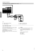
Only for cascades
B
B
C
C
C
30
32
31
+VBus-
14
13
S7
16
15
S8
B
30
32
31
+VBus-
14
13
S7
16
15
S8
A
A
30
32
31
+VBus-
14
13
S7
16
15
S8
30
32
31
+VBus-
14
13
S7
16
15
S8
Fig.8
A
Cascade master control unit
B
Cascade slave control unit
C
VBus cable
Make the connection between the individual control
units in the cascade:
Connect the VBus cable (accessories) to the VBus
connection of the control units as shown in Fig. 8.
!
Please note
Interchanged connections result in incorrect
data transfer.
Never interchange cores.
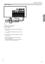
Power supply
Regulations
Connect the power supply and implement all safety
measures (e.g. RCD circuit) in accordance with
IEC 60364-4-41, the connection requirements of your
local power supply utility, and VDE or national regula-
tions.
■
Protect the control unit power cable with an appropri-
ate fuse.
■
Disconnect the system by means of a device that
simultaneously separates all non-earthed conductors
with at least 3 mm contact separation.
We also recommend installing an AC/DC-sensitive
RCD (RCD class B
) for DC (fault) currents
that can occur with energy efficient equipment.
Connection
Danger
Incorrect core allocation can result in serious
injury and damage to the appliance.
Never interchange cores "L" and "N".
L
Brown
N
Blue
PE Green/Yellow
Installation sequence
Connecting the VBus
5517 095 GB
Installation
Содержание VITOTRANS 353
Страница 50: ...50 5517 095 GB ...
Страница 51: ...51 5517 095 GB ...


