background image

6

Symbol

Meaning

Reference to other document containing
further information
 

1.

Step in a diagram:
The numbers correspond to the order in
which the steps are carried out.

Warning of material losses and environ-
mental pollution
 
 
Live electrical area
 
 
Pay particular attention.


Component must audibly click into place.
or

Acoustic signal

Fit new component.
or

In conjunction with a tool: Clean the sur-
face.

Dispose of component correctly.
 
 
Dispose of component at a suitable collec-
tion point. Do 

not

 dispose of component in

domestic waste.
 

The steps in connection with commissioning, inspec-
tion and maintenance are found in the "Commission-
ing, inspection and maintenance" section and identified
as follows:

Symbol

Meaning

Steps required during commissioning

Not required during commissioning

Steps required during inspection

Not required during inspection

Steps required during maintenance

Not required during maintenance

Intended use

The appliance is intended solely for installation and
operation in sealed unvented heating systems that
comply with EN 12828, with due attention paid to the
associated installation, service and operating instruc-
tions. It is only designed for heating up heating water
that is of potable water quality.

Intended use presupposes that a fixed installation in
conjunction with permissible, system-specific compo-
nents has been carried out.

Commercial or industrial usage for a purpose other
than heating the building or DHW shall be deemed
inappropriate.

Any usage beyond this must be approved by the man-
ufacturer in each individual case.

Incorrect usage or operation of the appliance (e.g. the
appliance being opened by the system user) is prohibi-
ted and will result in an exclusion of liability. Incorrect
usage also occurs if the components in the heating
system are modified from their intended use (e.g. if the
flue gas and ventilation air paths are sealed).

Information

Symbols

5671704

Information

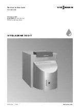
Содержание VITOLADENS 300-T

Страница 1: ...Service instructions for contractors VIESMANN Vitoladens 300 T Type VW3B 35 4 to 53 7 kW Oil Unit condensing boiler VITOLADENS 300 T 5671704 GB 7 2019 Please keep safe...

Страница 2: ...authorised by the installer Regulations to be observed National installation regulations Statutory regulations for the prevention of accidents Statutory regulations for environmental protection Codes...

Страница 3: ...g system Ventilate the installation site Close the doors to living spaces to prevent flue gases from spread ing What to do if water escapes from the appliance Danger If water escapes from the applianc...

Страница 4: ...the same time this can lead to a reverse flow of flue gas Danger The simultaneous operation of the boiler and appliances that extract air to the outside can result in life threatening poisoning due t...

Страница 5: ...ommissioning inspection and maintenance 8 3 Commissioning service reports 15 4 Specification 16 5 Shutdown and disposal Final decommissioning and disposal 17 6 Certificates Declaration of conformity 1...

Страница 6: ...d during maintenance Not required during maintenance Intended use The appliance is intended solely for installation and operation in sealed unvented heating systems that comply with EN 12828 with due...

Страница 7: ...7 Information about spare parts can be found on the Viessmann spare parts app Information Spare parts lists 5671704 Information...

Страница 8: ...l filter if installed 12 10 Cleaning the condensate drain pipe and trap and reconnecting to the drainage system 12 11 Checking the connections on the flue gas side for tightness 13 12 Checking the con...

Страница 9: ...up water with a water hardness in excess of the following values must be soft ened e g with a small softening system for heating water Total permissible hardness of the fill and top up water Total hea...

Страница 10: ...the boiler for cleaning 1 Remove contamination from the connector using a vacuum cleaner 2 Thoroughly flush the heating surface with water Please note Prevent components of the stainless steel heat e...

Страница 11: ...s a normal sign of use It has no bearing on the function or service life of the heat exchanger To remove hard deposits use slightly acidic chloride free cleaning agents based on phosphoric acid e g An...

Страница 12: ...e Part no for pH test strips 9517 678 Observe the neutralising system manufacturer s instructions 2 Reinstall the neutralising system in reverse order Checking the active charcoal filter if installed...

Страница 13: ...n a cold system 1 Drain the system until the pressure gauge indi cates 0 or close the cap valve on the diaphragm expansion vessel and reduce the pressure in this vessel 2 If the pre charge pressure of...

Страница 14: ...onnection for damage Adjusting the burner Burner service instructions Instructing the system user The system installer should hand the operating instruc tions to the system user and instruct the user...

Страница 15: ...ce Maintenance service Date By Maintenance service Maintenance service Maintenance service Date By Maintenance service Maintenance service Maintenance service Date By Maintenance service Maintenance s...

Страница 16: ...At a return temperature of 60 C C 67 62 63 Power consumption 4 at 100 of rated heating output W 250 340 340 30 of rated heating output W 84 113 113 2 Observe when sizing the chimney 3 Flue gas tempera...

Страница 17: ...e not part of ordi nary household waste For decommissioning the system isolate the system from the power supply and allow components to cool down where appropriate All components must be disposed of c...

Страница 18: ...rmity Manufacturer s declaration This product meets the requirements of the Efficiency Directive 92 42 EEC for condensing boilers Manufacturer s certificate according to the 1st BImSchV Germany We Vie...

Страница 19: ...ng 11 H Heating surface cleaning 10 I Intended use 6 M Mixer checking for ease of operation and tightness 14 N Neutralising system checking 12 P Pressure checking the system 13 R Room sealed operation...

Страница 20: ...Shropshire TF1 7YP GB Telephone 44 1952 675000 Fax 44 1952 675040 E mail info uk viessmann com Viessmann Werke GmbH Co KG D 35107 Allendorf Telephone 49 6452 70 0 Fax 49 6452 70 2780 www viessmann com...

Отзывы: