Viessmann Vitogas 050 ECD Series Скачать руководство пользователя страница 15

If an external electrical source is utilized, the boiler, when
installed, must be electrically grounded in accordance with the
requirements of the authority having jurisdiction or, in the
absence of such requirements, with the National Electrical
Code, ANSI/NFPA 70.

Boiler electrical requirements are 120V, 60 Hz, less than 12A.
The thermostat connections on the boiler must be connected
to a potential-free (or “dry”) contact such as a room thermostat,
end switch of a zone valve or dry contact of an indoor/outdoor
control.

See wiring diagram in rear of manual and wiring label on
boiler. Viessmann reserves the right to substitute electrical
components as necessary. The boiler wiring label takes
precedence.

Caution
Label all wires prior to disconnection when servicing controls.
Wiring errors can cause improper and dangerous operation.
Verify proper operation after servicing.

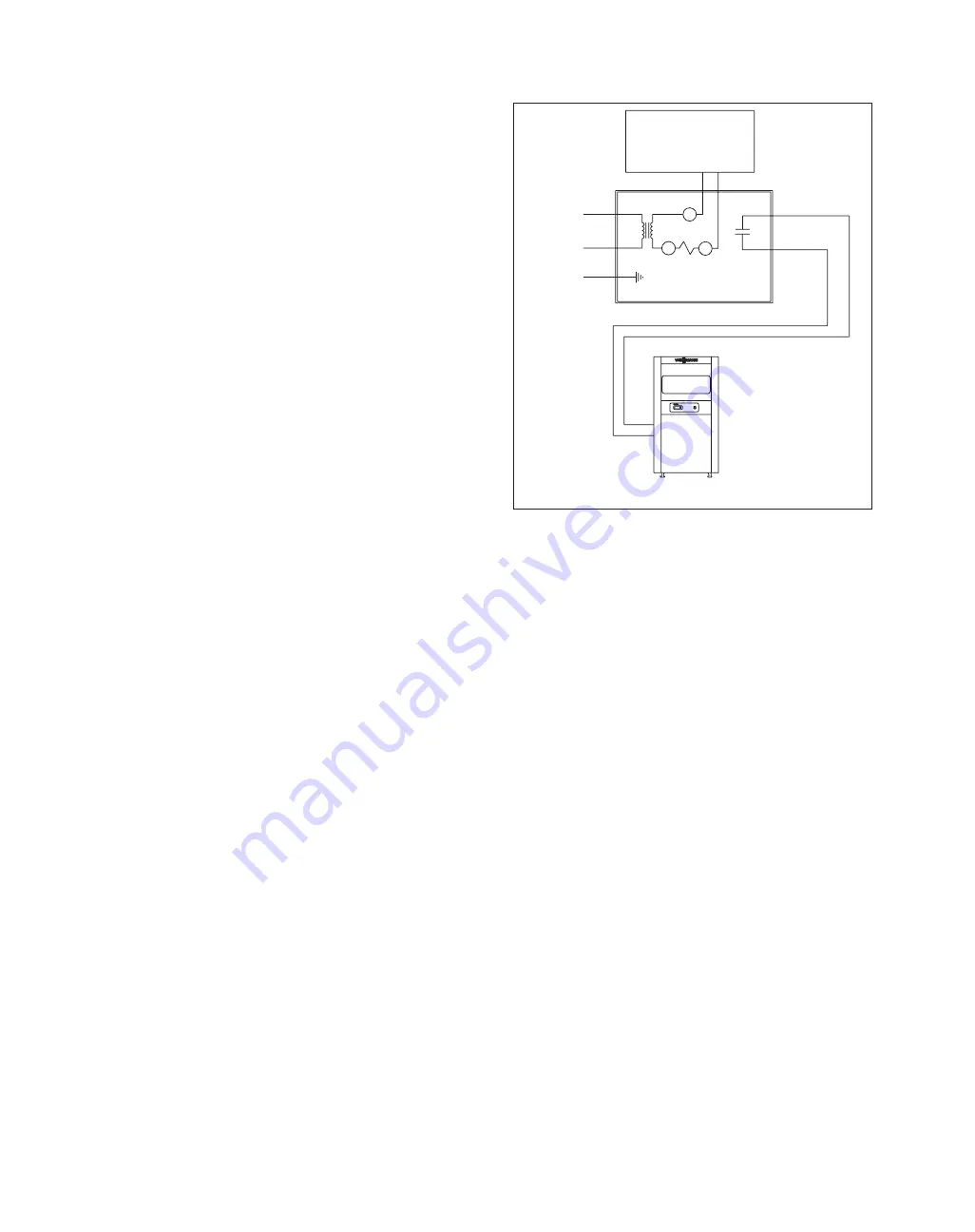
Electronic thermostat connection
For those installations where an electronic set-back thermostat
is used, an isolation relay may be necessary (see Fig. 9g). Any
electronic thermostat that constantly requires current from the
boiler transformer will require an isolation relay. For example
when installing a Honeywell Chronotherm, use an isolation
transformer relay (as shown in Fig. 10) to provide current for
the electronic thermostat.

System start-up procedure
If the system was shut down for an extended period of time,
have a qualified service technician restart and recondition your
system. Refer to lighting instructions on page 18.
1.

Check if all national and/or local rules and regulations
have been adhered to on this installation. Do not attempt
to start the boiler if you smell gas. If you smell gas, open
windows. Do not touch electrical switches, extinguish any
open flame, close all gas valves immediately. Call your
gas supplier immediately from a neighbor’s phone.

2.

Check system for proper water fill (cold fill pressure).
Make sure that complete system is properly vented of air.
Adjust automatic feed valve to proper desired fill pressure
between 12-15 psig.
Do not tamper with the unit or controls.
Never burn garbage or paper in the unit or leave
combustible materials around it.

Additional attention must be given to the following
paragraphs
1.

Once system water is heated, deactivate circulating
pump/boiler and vent system of any remaining air within
piping, radiation and boiler.

2.

Check for proper boiler circulation, pump, zone valve,
thermostat or operating control functions.

3.

Check high limit aquastat by dialing it to a setting below
the water temperature in the boiler. The gas burner must
be deactivated. Turning the dial back to a setting higher
than the present boiler water temperature must result in
reactivation of gas burner.

4.

Cycle boiler on and off with the room thermostat (or other
operating control) to verify that the burner shuts down when
the room thermostat is adjusted below room temperature.

Annual shut-down
If boiler is used for comfort heating only and not used with an
indirect-fired domestic hot water storage tank, the
boiler/heating system should be shut down during the summer
time.
1.

Turn down operating control (thermostat).

2.

Disconnect main power switch.

3.

Close main gas shut-off valve and turn knob on gas valve
to “off” (see Figs. 6 and 7).

ATTENTION

If system is shut down during the heating season and subject
to freezing temperatures and is not filled with antifreeze for
protection, the system including the boiler must be drained of
water. Valve before automatic feed valve (if installed) must be
closed; any other valves, air vents and drain valves must stay
open.

Advise the operator/ultimate owner
1.

Of the proper system operation sequence.

2.

Explain the equipment as well as the need for 
combustion air.

3.

Demonstrate an emergency shut-down, what to do and
what not. Refer to lighting instructions on page 18.

4.

Explain that there is no substitute for proper maintenance
to help ensure safe operation.

Before leaving jobsite
Fill in and sign warranty card for boiler and hand over to owner
for record keeping.

Maintenance

Inspections during heating season

15

Fig. 10
Isolation relay for electronic thermostat

Honeywell
Chronotherm
electronic set-back
room thermostat

H

N

G

WR 8A02A-8
Isolation transformer relay

R

C

G

To boiler
thermostat
connections

T-T on 
terminal strip

120V

24V

Содержание Vitogas 050 ECD Series

Страница 1: ...ct the electrical supply to the pump Instead shut off the gas supply at a location external to the appliance Contents Page Technical Data 3 Boiler handling location 3 Flushing of existing piping 4 Vent damper installation 4 Closet installation 5 Combustion air supply 6 Installation on combustible floor 8 Boiler water piping 8 Honeywell adjustable high limit aquastat 9 Circulating pump 9 Initial sy...

Страница 2: ...fresh outside combustion and ventilation air Neglecting to perform necessary maintenance can cause unsafe operation Do not store chemicals containing chlorine or other corrosive materials near the boiler such as bleach cleaning solvents detergents acids hair spray spray cans paint thinners paint water softener salt refrigerants Warning Installers must follow local regulations with respect to insta...

Страница 3: ...ciency ECD 65 65 000 Btu h 53 950 Btu h 350 mm 5 1 2 11 4 3 2 9 9 ltr 106 kg 83 7 83 19 kW 16 kW 14 2 6 USG 233lbs ECD 80 80 000 Btu h 66 400 Btu h 350 mm 5 1 2 11 4 3 2 9 9 ltr 106 kg 83 5 83 23 kW 19 kW 14 2 6 USG 233 lbs ECD 100 100 000 Btu h 83 000 Btu h 450 mm 6 1 2 11 4 4 3 13 2 ltr 130 kg 83 5 83 29 kW 24 kW 173 4 3 5 USG 285 lbs ECD 115 115 000 Btu h 95 450 Btu h 450 mm 6 1 2 11 4 4 3 13 2...

Страница 4: ...n if necessary The boiler must be installed in an indoor heated space The boiler should be located near a floor drain Do not install boilers on carpeting Install on non combustible floor If the boiler is to be installed on combustible floors or on a mezzanine it should be equipped with a special base pan Please reference the Viessmann Price List Typical boiler piping is shown in Fig A Vent damper ...

Страница 5: ...ow the vent damper manufacturer s instructions to leave the vent damper in the Service or Hold Open Damper Effikal mode by using the service switch on the damper motor Vent damper blade should stay open and boiler should operate normally 2 If the procedure in 1 does not work remove vent damper install transitional piece of vent pipe and disconnect 6 pole plug from 3 pole plugs Connect the 3 pole p...

Страница 6: ...nto the living space Any home with bathroom or kitchen exhaust fans or heat recovery ventilator units should have outside air intake You must check with local authorities municipal building department gas utility for combustion air requirements particular to your area Caution Whenever your boiler is installed in a structure with airtight features such as vapor barrier or tight insulation there mus...

Страница 7: ...ings or ducts supplying air directly from the outside If there is any doubt about the combustion air supply install ducts directly to the outside for fresh air 2 If the boiler is installed in a confined space within the building a space with a volume less than 50 ft3 per 1 000 Btu h of input for all gas burning equipment then adequate air for combustion must be provided by two permanent openings o...

Страница 8: ...red with sheet metal at least 24 ga thick 4 The base must extend beyond the boiler enclosure by at least 150 mm 6 on all sides 5 The blocks must be placed to provide an unbroken concrete surface under the boiler with the hollows running continuously and horizontally to allow air circulation Boiler water piping Install pressure relief valve and pressure gage directly to boiler supply No isolation v...

Страница 9: ...oiler terminal strip Circulating pump supplied by others Failure to connect pump aquastat will significantly shorten life expectancy of boiler heat exchanger Pump aquastat is factory set at 116 F Alternate aquastat is available at 104 F Note to Fig 4a For multi zone systems using zone pumps one pump usually the one serving the main living area should be dedicated to operate with the pump aquastat ...

Страница 10: ...ather responsive control of an underfloor heating system 1 Install full size bypass as shown below 2 Use valve in bypass and valve in supply line to balance flow so that boiler water temperature quickly reaches 140 F or higher Use globe valve or ball valve 3 Bypass line should be minimum 12 long 4 Bypass will lower flow rate through boiler to allow higher average water temperature rise Water flow ...

Страница 11: ...n 1 Seal any unused openings in the common venting system 2 Visually inspect the venting system for proper size and horizontal pitch and determine there is no blockage or restriction leakage corrosion or other deficiency which would cause an unsafe condition 3 Insofar as is practical close all building doors and windows and all doors between the space in which the appliances remaining connected to...

Страница 12: ...ng to boiler according to local utility requirements Identify the main shut off valve as such with a tag and familiarize owner of boiler with this valve Support piping by proper suspension method Piping must not rest on or be supported by boiler Testing gas pipe The boiler and its gas connection must be leak tested before placing the boiler in operation Use only the gas stated on the boiler rating...

Страница 13: ...ON Do not exceed input rating stamped on rating plate of boiler 1 Close main gas shut off valve 2 Disconnect main power supply to boiler 3 Remove plug 1 8 on manifold Install test plug and connect U tube manometer or equivalent 4 Place boiler burner in operation 5 Read manifold gas pressure and compare with stamped rating on rating plate If necessary adjust pressure on gas valve If using meter clo...

Страница 14: ...test edition In Canada all electrical connections must be in accordance with Canadian Electrical Code C22 1 Part 1 latest edition 14 Fig 9e ECD 180 200 pilot location Fig 9f Pilot burner flame for Q3451A2012 Sensor tip must be in pilot flame Proper flame adjustment Igniter sensor 1 4 to 1 2 6 to 13 mm PILOT PRESSURE FOR Q345A PILOT Natural Gas 5 7 w c Propane Gas 8 10 w c Left Right Flame Roll Out...

Страница 15: ...er with the unit or controls Never burn garbage or paper in the unit or leave combustible materials around it Additional attention must be given to the following paragraphs 1 Once system water is heated deactivate circulating pump boiler and vent system of any remaining air within piping radiation and boiler 2 Check for proper boiler circulation pump zone valve thermostat or operating control func...

Страница 16: ...15 Inspect ignition system Check igniter for cracks or other deterioration Replace if necessary 16 Reverse steps 4 through 11 to reassemble boiler Seal draft hood to casting using a high temperature RTV type sealant Additional check points of annual service inspection Check flue pipe condition chimney connection and chimney itself both inside and outside for rust deterioration blockage or leakage ...

Страница 17: ...wer supply Wait for boiler to cool down Reset aquastat Replace Replace pilot orifice Replace ground wire Turn knob to on Check position of main gas shut off valve or purge gas line of air Replace Replace Chimney or vent obstruction needs to be removed Clean heat exchanger Replace Replace Replace NATURAL GAS PROPANE GAS GAS CONTROL LIST HONEYWELL PART NO HONEYWELL PART NO Gas Valve ECD VR8204P1007 ...

Страница 18: ...ty information above on this page 2 Set the thermostat to the lowest setting 3 Turn off all electric power to the appliance 4 This appliance is equipped with an ignition device which automatically lights the pilot Do not try to light the pilot by hand 5 Remove control access panel 6 Turn gas control knob clockwise to OFF 7 Wait five 5 minutes to clear out any gas Then smell for gas including near ...

Страница 19: ...HL2 Fixed manual reset high limit aquastat set at 120 C 248 F H Hot N Neutral G Ground Field supplied PA Pump aquastat control with fixed settings Pump on at 40 C 104 F Pump off at 33 C 91 F If any of the original wires supplied with the appliance must be replaced replace with 105 C rated wire or its equivalent 24V thermostat anticipator 0 8A 24V vent damper Optional wall vent system Molex connect...

Страница 20: ...HL1 Fixed manual reset 248 F aquastat T1 T1 S3 S3 T2 T2 F F F S3 S3 T2 T2 T1 T1 N 120V 60Hz less than 12A PA Pump 120V 4A Max Yellow Orange Blue Black 120V 24V SHL1 BVS SHL2 FRS Room thermostat 24V Effikal 24V gas valve L MV MV PV PV GND BRN 24V GND 24V S P A R K Field supplied See Fig 4a for wiring pumps over 4A Use isolation relay for pumps over 4A See Fig 10 for electronic thermostat wiring Fig...

Страница 21: ...cation for the ECD 180 ECD 200 20 48 47 46 45 44 43 42 41 40 39 38 37 36 35 34 32 33 29 30 28 27 26 25 24 23 22 21 18 15 16 17 14 13 12 11 10 9 6 8 7 5 4 3 2 1 Honeywell Vitogas 050 ECD Series Cast Iron Atmospheric Gas Fired exploded view example of ECD 140 ECD 155 21 Inspection opening for heat exchanger ...

Страница 22: ...9544 217 9543 923 1 1 9544 218 9543 924 1 1 9544 219 9543 925 1 1 7 Mid panel 9544 220 9543 887 1 1 9544 221 9543 888 1 1 9544 222 9543 889 1 1 9544 223 9543 890 1 1 8 Control panel 9544 224 9543 877 1 1 9544 225 9543 906 1 1 9544 226 9543 907 1 1 9544 227 9543 908 1 1 9 Drafthood assembly 9544 228 9543 926 1 1 9544 229 9543 927 1 1 9544 230 9543 928 1 1 9544 231 9543 929 1 1 10 Drafthood strap 95...

Страница 23: ... 071 9507 073 9507 071 9507 072 9507 614 9507 073 LP 0 2000 ft 9507 652 9537 208 9507 640 9507 653 9507 641 9507 653 9507 641 9537 208 2000 4500 ft 9507 652 9537 208 9507 640 9507 653 9507 641 9507 653 9507 641 9537 208 4500 7000 ft 9507 652 9507 653 9507 652 9507 641 9507 640 9507 641 9507 640 9507 653 24 Stainless steel 9507 642 9507 642 1 1 2 2 3 3 4 4 burner tube 25 Burner mounting 9507 051 95...

Страница 24: ... 1 1 1 1 40 Insulation fiber plate Left side 7205 515 7205 515 1 1 1 1 1 1 1 1 Right side 7205 514 7205 514 1 1 1 1 1 1 1 1 41 Hex bushing 9543 718 9543 718 2 2 2 2 2 2 2 2 11 2 x 11 4 42 Pressure relief valve 9542 940 9542 940 1 1 1 1 1 1 1 1 3 4 30 psig 43 Pressure gage 9542 939 9542 939 1 1 1 1 1 1 1 1 0 100 psig 44 Flame roll out switch 9543 878 9543 878 1 1 1 1 1 1 1 1 60T14 140F 140 F 45 Tra...

Страница 25: ...ger must be kept clean for safe operation Maintenance record Year Service contractor Clean boiler Check for proper supply Vent system inspected for soot Burner serviced and name phone number heat exchanger of combustion air leaks deterioration proper draft combustion test adherence to codes blockage performed 1 2 3 4 5 6 7 8 9 10 11 12 13 14 15 16 17 18 19 20 ...

Страница 26: ......

Страница 27: ......

Страница 28: ...Island 02886 USA Waterloo Ontario N2V 2G5 Canada Tel 401 732 0667 Fax 401 732 0590 Tel 519 885 6300 Fax 519 885 0887 www viessmann us com mail viessmann us com www viessmann ca mail viessmann ca 5167 445 Technical information subject to change without notice Printed on environmentally friendly recycled and recyclable paper ...

Отзывы: