23
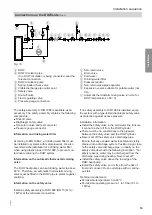
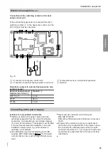
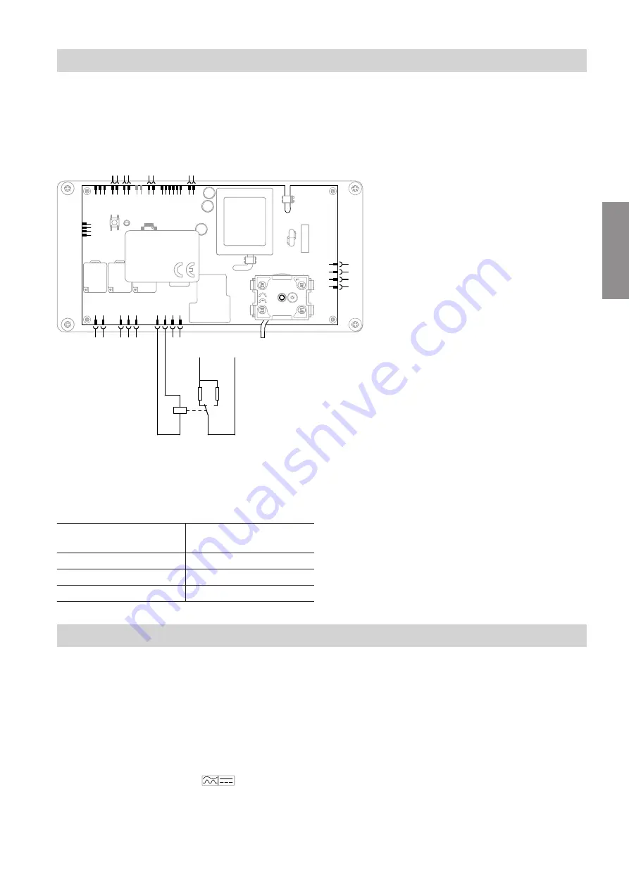
Connection to the switching contact on the heat
pump control unit
If the external heat generator is connected directly to
switching contact
A
on the heat pump control unit, the
230 V signal must be converted.
N
L
A1
A2
K1
A
B
C
D
Fig. 19
A
Connection to heat pump control unit
B
Connection to external heat generator control unit
C
Temperature sensor, external heat generator
D
Resistor
Resistance subject to external heat generator tem-
perature sensor
External heat generator
temperature sensor
C
Resistor
D
NTC 10 k
Ω
2.2 k
Ω
Pt500
680
Ω
Pt1000
1.3 k
Ω
Connecting to the power supply
Isolators for non-earthed conductors
■
Install an isolator in the power cable to provide
omnipolar separation from the mains for all active
conductors, corresponding to overvoltage category
III (3 mm) for full isolation. This isolator must be fitted
in the permanent electrical installation in line with
installation requirements, e.g. mains isolator or
upstream circuit breaker.
■
We additionally recommend installing an AC/DC-
sensitive RCD (RCD class B
) for DC (fault)
currents that can occur with energy efficient equip-
ment.
■
Select and size residual current devices to
DIN VDE 0100-530.
RCD with a differential current that does not exceed
30 mA.
■
Implement the mains connection as a permanent
connection (3-core cable NYM). If the mains connec-
tion is made with a flexible power cable, the earth
conductor should be min. 1 cm longer so that the live
conductors are pulled taut first in the event of strain
relief failure.
■
Installation sequence
Electrical connections
(cont.)
6136003
Installation


