


31
5443 109 v1.9
Pyrot Technical Data
Electrical
Vitocontrol Accessories
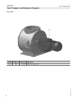
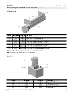
Triggering System for external drive
Function:
Starttec, motor soft start for optimized connection of an
external conveyor drive or rotary valve without reversal.
A CAN bus is used to directly connect the motors to the
gentle start-up system via the Ecotronic. Temperature-
monitored and protected against overloading. Its
electronic circuit breakers are wear-free, even at high
switching frequencies.
Supplied with:
- Starttec completely integrated in the control cabinet
- Parameter assignment for the drive function
- Input in the control cabinet for safety end switch on
the maintenance cover
- Output in the control cabinet for external conveyor
drive
Customer supplied:
- Delivery and/or installation of safety end switch for
the external conveyor drive
Note:
Only for PYROT. Starttec is built into the control
cabinet for the boiler plant.
Only possible with defined, limited material feed
facility (upstream conveyor auger)
Triggering System for external drive with light barrier
Function:
Starttec motor starter for optimized connection of an
external conveyor drive without reversal. A CAN bus is
used to directly connect the motors to the gentle start-up
system via the Ecotronic. Temperature-monitored and
protected against overloading. Its electronic circuit breakers
are wear-free, even at high switching frequencies.
Additional protection of the external drive through level-
monitoring system of the further feed system by means
of a light barrier. The light barrier connects directly to
the Starttec for the continuing feed system, affecting the
extraction system.
Supplied with:
- Starttec completely integrated in control cabinet
- Parameter assignment for the drive function
- Input in the control cabinet for safety end switch on
the maintenance cover
- Output in the control cabinet for external conveyor
drive
- Infrared light barrier, level-monitoring system for fuel
Customer supplied:
- Delivery and/or installation of safety end switch for
the external conveyor drive
Note:
Only for PYROT. Starttec is built into the control
cabinet for the boiler plant.
Note:
The control system components below are reserved
for the PYROT Single-unit System.
With the PYROT Double-unit System, these
functions are included in the Mastercontrol.
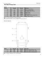
Hot Water Storage Tank Management System 3 Sensors
Function:
Using a heat accumulator improves the modulating output
operation of the PYROT grate firing system. In addition,
sudden heat requirement peaks are covered.
The accumulator’s load of heat is detected by the
temperature sensors. The firing power is adapted to
the accumulator’s degree of loading.
Supplied with:
- Two additional KTY sensors with sensor well,
1/2“ x 280 mm
External Request ON/OFF
Input for switching the system on and off automatically
by an external potential-free N.O. contact.
Operational Message
Function:
System status “Operating Load” indication; from operation
of the boiler pump to higher-level control.
Supplied with:
- Floating output (operational message)
Output signals 0 - 10 V
Function:
The system includes output of the boiler in the form of
a voltage signal and preparation for connection to receive
a maximum limitation of the boiler output.
Supplied with:
- Output of the boiler, 0 - 10 V
- Reception and processing of an external output
limitation
0 - 0.5 V..... OFF
0.6 - 3 V..... Standby
3.1 - 10 V... 30% to 100% output operation
Note:
Installation of “Output signals 0 - 10 V” is possible
according to “QM for Wood Heating Systems”
irrespective of any additional control system
components to be used.