background image

Safety instructions 


VITOBLOC 200


CHP unit accessory • Operating and installation instructions • Remote reset


5838316 

 GB


Safety instructions 

General 

These operating instructions contain basic information that must be observed 
when installing and operating the communication module. They must therefore 
be read by the installer and relevant qualified technician(s) prior to installation 
and commissioning. They must always be available at the system. 

Identification 
of safety instructions 


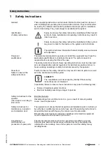
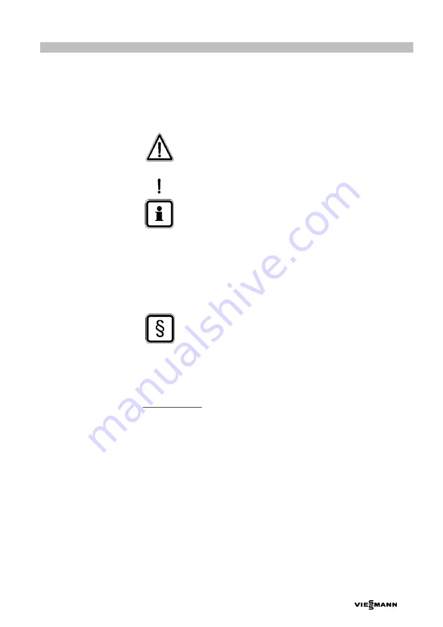
Failure to observe the safety instructions identified with this hazard 
symbol in these installation and operating instructions may result in 
risks to persons. 


Failure to observe the safety instructions identified with this symbol 
may result in risks for the device or the system and its functions. 


This symbol indicates information that will simplify work and ensure 
safe operation. 

Personnel 
qualifications 

The personnel designated to operate and install this equipment must have the 
appropriate qualifications to undertake this work. The system operator is 
responsible for ensuring that this is the case.  

The safety instructions listed in these operating instructions must be observed, 
as must all applicable national regulations for accident prevention and any in-
house working, operating or safety instructions issued by the operator. 

Risks from  
failure to observe the 
safety instructions 

Failure to observe the safety instructions may result in risks to persons as well 
as to the environment and the system.  

LIABILITY! 

The manufacturer will not accept any liability if these safety 
instructions are not observed. 

In particular, failure to observe these instructions may pose the following risks: 

  Failure of important system functions 

  Electrical hazards presenting a danger to persons 

Safety instructions for the 
operator  
(risk analysis according to 
EN 12100) 

Electrical hazards 

Hazards arising from electrical current, e.g. as a result of removing safety 
covers, must be prevented. 

Safety instructions for 
maintenance, inspection 
and installation work 

The operator must ensure that all inspection and installation work is carried out 
by authorised, qualified personnel who have used the operating instructions to 
acquaint themselves with the way the remote reset module works. 

Directly after work has been completed, all safety and protection equipment 
must be replaced and returned to full function. 

Unauthorised 
modifications and 
production of spare parts 

The remote reset module must not be converted or modified in any way. 
Original spare parts and accessories authorised by the manufacturer are 
important to ensure safety. Use of other parts can void the liability for any 
resulting losses. 

Содержание 7727448

Страница 1: ...Installation and operating instructions for contractors Remote reset CHP unit accessory for VITOBLOC 200 EM 6 15 to EM 530 660 5838316 GB 07 2019 ...

Страница 2: ...uctions 3 2 Function description 4 3 Version 5 4 Installation 6 5 Operation 8 5 1 General design and operating information 8 5 2 Step by step remote acknowledgement via VITODATA 10 6 Commissioning 13 7 Maintenance 13 8 Disposal 13 9 Appendix 14 9 1 Remote reset BBS 3000 wiring diagram 14 9 2 Remote reset BMS 2007 wiring diagram 18 ...

Страница 3: ...ntion and any in house working operating or safety instructions issued by the operator Risks from failure to observe the safety instructions Failure to observe the safety instructions may result in risks to persons as well as to the environment and the system LIABILITY The manufacturer will not accept any liability if these safety instructions are not observed In particular failure to observe thes...

Страница 4: ... binary signal via an internet connection For this purpose the Vitocom 300 LAN 3 is connected to the VITODATA server via the internet When the digital output ON OFF is actuated the corresponding switching command is sent from VITODATA to the Vitocom 300 The Vitocom 300 then switches the potential free DO output which connects the digital input for remote acknowledgement on the CHP unit display via...

Страница 5: ...e E 2 5 8 insulation bl 6 pce 2 Remote reset retrofit kit for EM 50 81 to EM 530 660 with BMS 2007 Part no 7727448 Article no Object short text Quantity 7870518 Remote reset EM 50 to 530 enclosure 1 pce 7870517 BMS 2007 display with reset function 1 pce 7870543 Label warning notice automatic start up 2 pce 7870542 Label warning sign automatic start up W018 2 pce 7870519 PVC control cable 5G2 5mm 1...

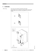
Страница 6: ...0 5838316 GB 4 Installation Wall mounting The enclosure of the retrofit kit is designed for wall mounting The wall brackets must be mounted on the enclosure for this For this purpose expansion plugs are used so that the mounting plate does not need to be removed Spanner size 10 Not for dynamic load ...

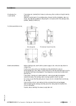
Страница 7: ...age free For the connection of the unit controller and the retrofit kit for remote acknowledgement the cables or leads listed in the bill of material must be used in accordance with the wiring diagram The stripped wire ends must be fitted with wire ferrules The cables or leads are routed outside the unit using standard installation material whereby the existing cable carrying systems should be use...

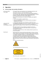
Страница 8: ...d the key removed so that the maintenance personnel working on site can exclude the possibility of an unexpected CHP unit start up There is therefore no risk of the system starting up The safety instructions which are obligatory according to the technical description operating instructions also remain valid when using the remote acknowledgement function This applies in particular to the use of the...

Страница 9: ...t knowledge of the status of the unit Since repeated remote acknowledgement can result in additional hazards e g repeated acknowledgement of the fault message Oil pressure min the possibility of remote acknowledgement must be limited to personnel trained by Viessmann Kraft Wärme Kopplung GmbH and only used in conjunction with remote monitoring TeleControl LAN in order to be able to assess the cond...

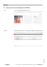
Страница 10: ... installation instructions Remote reset VITOBLOC 200 5838316 GB 5 2 Step by step remote acknowledgement via VITODATA Login 1 Log in to https vitodata300 viessmann com Selection 2 Select the relevant system in the example Testgerät Landsberg Vi KWK ...

Страница 11: ...Operation VITOBLOC 200 CHP unit accessory Operating and installation instructions Remote reset 11 5838316 GB 3 Select VC 300 LAN3 4 Operation menu 5 Select the digital output ...

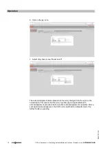
Страница 12: ...down menu Reset on off The acknowledgement takes place when the relay changes from the open to the closed state This means that the relay must be opened again after each acknowledgement procedure before another acknowledgement is possible After a successful acknowledgement the CHP unit is switched to automatic mode if no further faults are pending ...

Страница 13: ...general commissioning of the CHP system or in the case of retrofitting by the CHP unit manufacturer s technical service personnel or authorised contractors 7 Maintenance This accessory is maintenance free 8 Disposal Dispose of this product and its components in an environmentally responsible manner compliant with EU Directive 2012 96 EC Use public or private waste disposal companies ...

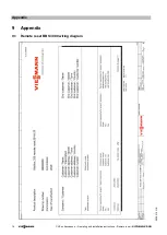
Страница 14: ...Appendix 14 CHP unit accessory Operating and installation instructions Remote reset VITOBLOC 200 5838316 GB 9 Appendix 9 1 Remote reset BBS 3000 wiring diagram ...

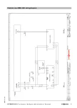
Страница 15: ...Remote reset BBS 3000 wiring diagram VITOBLOC 200 CHP unit accessory Operating and installation instructions Remote reset 15 5838316 GB ...

Страница 16: ...Remote reset BBS 3000 wiring diagram 16 CHP unit accessory Operating and installation instructions Remote reset VITOBLOC 200 5838316 GB ...

Страница 17: ...Remote reset BBS 3000 wiring diagram VITOBLOC 200 CHP unit accessory Operating and installation instructions Remote reset 17 5838316 GB ...

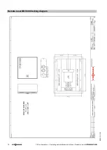
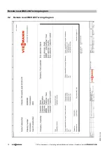
Страница 18: ...Remote reset BMS 2007 wiring diagram 18 CHP unit accessory Operating and installation instructions Remote reset VITOBLOC 200 5838316 GB 9 2 Remote reset BMS 2007 wiring diagram ...

Страница 19: ...Remote reset BMS 2007 wiring diagram VITOBLOC 200 CHP unit accessory Operating and installation instructions Remote reset 19 5838316 GB ...

Страница 20: ...Remote reset BMS 2007 wiring diagram 20 CHP unit accessory Operating and installation instructions Remote reset VITOBLOC 200 5838316 GB ...

Страница 21: ...Remote reset BMS 2007 wiring diagram VITOBLOC 200 CHP unit accessory Operating and installation instructions Remote reset 21 5838316 GB ...

Страница 22: ...Remote reset BMS 2007 wiring diagram 22 CHP unit accessory Operating and installation instructions Remote reset VITOBLOC 200 5838316 GB ...

Страница 23: ...Notes VITOBLOC 200 CHP unit accessory Operating and installation instructions Remote reset 23 5838316 GB ...

Страница 24: ...24 5838316 GB Subject to technical modifications Viessmann Werke GmbH Co KG D 35107 Allendorf Tel 49 0 6452 70 0 Fax 49 0 6452 70 2780 www viessmann de ...

Отзывы: