background image

56 

Software Set-Up Procedures

IM-HC 599871 0321 RABS

5  Software Set-Up Procedures

5.1 

Software Operation Method Requirements

The requirements for each software operation method are listed below.

5.1.1  Method 3 – Local Operation via Software

Initial set-up requires either a computer or a tablet; a smart 

phone can not perform the initial set-up.

In addition to operation method 2:

„ 

The WLAN module is connected to the control unit.

„ 

A WLAN-capable end device.

5.1.2  Method 4 – Remote Operation via Software

Initial set-up requires either a computer or a tablet; a smart 

phone can not perform the initial set-up.

In addition to operation method 3:

„ 

A WLAN-capable router with WPA2 security.

„ 

Internet access.

5.2  Method 3 

 Local Operation via Software

The Radiant Auto-Balancing System has been set and is operating as 

described in Configuration level 2; additionally, a WLAN module is 

required. The connection of the control unit to WLAN-capable end 

devices gives you access to convenient control functions.
Settings via the operating software

Ä

6.1 “Operating Software” on page 72

5.2.1  Overview of Functions

Use the operating software to configure/display the following functions:

„ 

Power level

„ 

Room temperature “Target”

„ 

Room temperature “Actual”

„ 

Supply temperature

„ 

Return temperature

„ 

Heating profiles (day/night)

„ 

6 switching points per day for heating operation

„ 

Limitation of the adjustable room temperatures warm/cold

„ 

Activation of go-away mode

„ 

Room prioritization

„ 

Long-term analysis of supply temperature

„ 

Fault diagnosis

Access to the settings can be protected by means of a password.

Содержание RABS 1250.7US

Страница 1: ...Installation Manual Radiant Auto Balancing System RABS For Radiant Heating Systems 03 2021...

Страница 2: ...Front Room North Thermostat 2 Loop Circuit 5 Loop Circuit 6 Loop Circuit 7 Loop Circuit 8 Loop Circuit 9 Loop Circuit 10 Loop Circuit 11 Loop Circuit 12 Hardware Identification Information for the Ins...

Страница 3: ...3 3_ Accessories_ __________________________________ 19 Range Extender_____________________________________ 19 Power Adapter for Range Extenders and or Thermostats_ 20 2 4_ Technical Data____________...

Страница 4: ...nting Versions___________________________________ 41 Using the Mounting Frame____________________________ 41 Mounting the Thermostat to the Wall___________________ 42 Mounting the Thermostat on a Conc...

Страница 5: ...___ 56 5 2_ Method 3 Local Operation via Software_ ______ 56 5 2 1_ Overview of Functions_ _________________________ 56 5 2 2_ Setting Up a WLAN Module_ _____________________ 57 5 2 3_ Starting the Op...

Страница 6: ...Units Menu_____________ 82 6 1 13_Control Units Overview Control Units____________ 83 6 1 14_Sorting and Renaming Rooms_ __________________ 84 6 1 15_Activating Circuit Offset_________________________...

Страница 7: ...cuit Hub_ ______________________ 96 8 3 3_ Exchanging the Thermostat______________________ 97 8 3 4_ Replacing the Range Externder_ _________________ 97 8 3 5_ Replace Supply Temperature Sensor_______...

Страница 8: ...ost current Viega technical literature please visit www viega us The firmware and software for RABS are subject to updates For the most current versions please visit www rabs viega us The WLAN Module...

Страница 9: ...operator or owner after completing installation and set up 1 4 Safety Notices DANGER Risk of electric shock An electric shock can lead to burns serious injury and even death Electrical work may only...

Страница 10: ...N 60730 2 14 2009 Particular Requirements for Electrical Actuators FCC Part 15 Subpart B FCC Part 15 Subpart C IEC 60950 1 Canada CAN CSA E60730 1 2015 Ed 5 CAN CSA E60730 2 9 2018 Ed 4 CAN CSA E60730...

Страница 11: ...etween the equipment and receiver Connect the equipment into an outlet on a circuit different from that to which the receiver is connected Consult the dealer or an experienced radio TV technician for...

Страница 12: ...r different operation methods that complement each other The user can control zones through power levels thermostats and operation software A local end device can access the operation software by conn...

Страница 13: ...set for each thermostat Unoccupied Mode increases energy efficiency by reducing demand during unoccupied periods Dynamic long term temperature analysis helps optimize the system settings for increased...

Страница 14: ...RS 232 RESET Figure 2 Control unit 1 Integrated power adapter 2 Socket for long ribbon cable 31 5 inches 3 Male connector for supply sensor 4 Socket for future function 5 Male connector for WLAN modul...

Страница 15: ...b 4 Threaded connection to the return valve on the return manifold For mounting instructions see 3 3 3 Mount the Powerheads on page 33 Return Sensor Port Model 1250 2US The return sensor port connects...

Страница 16: ...he control unit uses this information to determine how to prioritize and or distribute heat to each circuit in the system After the control unit analyses the system parameters it transmits control inf...

Страница 17: ...Subcomponents 1 2 3 4 5 Figure 7 Thermostat subcomponents 1 Metal plate 2 Mounting frame 3 Housing and display faceplate 4 Two alkaline AA batteries 5 Screws and drywall anchors 3 16 inch A123C45E 1...

Страница 18: ...e thermostat set up procedure see 4 3 Method 2 Zone Control via Thermostat on page 46 WLAN Module Model 1250 4US The WLAN module connects the control unit to end devices It connects to the control uni...

Страница 19: ...MHz Use a range extender when the signal from a thermostat to the control unit is too weak Range extenders require the RABS power adapter to operate Range extenders operate in parallel not in series...

Страница 20: ...tats The power adapter plugs into standard wall sockets and converts 120V AC to 7 5V DC Power adapters are required for range extenders They are optional for thermostats The cable is 39 inches long Fi...

Страница 21: ...aximum 5 to 95 Ambient temperature minimum maximum 32 to 122 F IP Code IP 20 Input voltage 120V AC 50 60 Hz Operating voltage 24V DC Power consumption maximum 12 active circuits 45 W continuous output...

Страница 22: ...tting M30 1 5 Circuit Hub Underwriters Laboratory UL conformity UL 60730 1 UL 60730 2 9 Dimensions W H D 1 78 x 1 44 x 1 14 inch Operating temperature minimum maximum 32 to 140 F Relative humidity min...

Страница 23: ...oltage 3V DC Battery type and size Two 1 5V DC alkaline AA LR6 Battery service life Approximately 2 years Setting range minimum maximum 41 to 86 F Display range minimum maximum 32 to 99 F Measuring di...

Страница 24: ...minimum maximum 32 to 113 F Relative humidity minimum maximum 5 to 95 IP Code IP 20 Input Voltage 5 to 7 5V DC Operating voltage 3V DC Cable length 39 inches Radio Connection see Control Unit Power A...

Страница 25: ...nts 2 5 1 Hardware Manifolds RABS components must used in conjunction with a Viega 1 inch stainless steel manifold Model 2804 or Model 2879 Power Requirements RABS requires 120V AC standard wall outle...

Страница 26: ...ating circuits Immediate response to priority zone heat demands The functions and features on RABS can be configured to meet these requirements While a good design is critical to the success of any ra...

Страница 27: ...can be set using the button on a circuit hub or via the operation software See 4 2 Method 1 Zone Control via Power Level on page 45 to learn how to set the power level on a circuit 2 6 2 Method 2 Zone...

Страница 28: ...ware on page 56 to learn how to create a local connection with an end device 2 6 4 Method 4 Remote Operation via Software If the end user connects the WLAN module to a local WLAN then the operation so...

Страница 29: ...TICE Defective components must be replaced Do not attempt to repair them 3 2 Assembly Information 3 2 1 Installation Requirements Power The RABS control unit requires access to a 120V wall outlet with...

Страница 30: ...es dimensions inches required for mounting RABS components Control Unit Figure 15 Control unit installation dimensions Leave room for the power cable and the component cables Powerhead Figure 16 Power...

Страница 31: ...nd check the thermostat s signal strength before selecting the control unit s installation location See 4 3 4 Logging the Thermostat into the Control Unit on page 48 To check the thermostat s signal s...

Страница 32: ...Mounting Sequence X Thread the return header nut onto the return header and tighten by hand X Use a 20mm wrench to align the return sensor port Z The port for the return temperature sensor must point...

Страница 33: ...ifold Required materials The long ribbon cable 31 5 inches that comes with the control unit and the short ribbon cable 3 inch that comes with each circuit hub Note there will be a spare short ribbon c...

Страница 34: ...his procedure until all circuit hubs are chained together in series The last circuit hub will have an empty socket The short ribbon cable 3 inch that comes with it does not get used X Plug each powerh...

Страница 35: ...r the mounting surface material Screwdriver Scissors to cut the tail off of the supply sensor cable tie Overview of Control Unit Sockets X Push in on the housing lock on the right side of the control...

Страница 36: ...5 inches long Verify both ends of each cable can reach their contact points before deciding where to install the control unit Maintain at least two inches of clearance around the housing faceplate to...

Страница 37: ...page 37 WLAN module 3 3 8 WLAN Module on page 44 External output on page 38 Socket for future radiant cooling function Socket for Future Radiant Cooling Function on page 39 Connect the Circuit Hubs t...

Страница 38: ...ly sensor cable into the control unit socket second from the left until it clicks securely X Press the supply sensor cable into the strain relief recess below the socket to ensure the housing faceplat...

Страница 39: ...that the control unit is unplugged or that the circuit is shut off Then remove the housing faceplate Page 35 X Attach one end of some two wire 18 AWG to the cable clip terminal on the external output...

Страница 40: ...ng the Radio Connection on page 49 Verify the thermostat can be accessed readily 2 inches of free space on all sides is required to replace the batteries Mounting the Thermostat on a Concealed Socket...

Страница 41: ...both the thermostat and the range extender After fastening the mounting frame to the wall or a concealed socket place the casings onto the frame They will be held in place by two tabs When mounting th...

Страница 42: ...terials are included with delivery X When mounting a thermostat screw the mounting frame directly to the wall or to a concealed socket X Place the thermostat on the mounting frame and press on it unti...

Страница 43: ...R 120 V voltage risk of electric shock De energize the circuit before connecting the power pack Radio amplifiers need a 120 V mains connection Only one range extender may be used in a radio link The c...

Страница 44: ...44 Installation and Assembly IM HC 599871 0321 RABS 3 3 8 WLAN Module Attach the WLAN module next to the control unit using the included double sided tape...

Страница 45: ...r source Two alkaline AA batteries Optional power adapter model 1250 7US Optional range extender s with power adapter s 4 1 3 Component Identification Viega recommends noting the serial number of each...

Страница 46: ...oftware 4 3 Method 2 Zone Control via Thermostat The control unit transceiver communicates with the thermostat s and range extender s at 916 MHz The WLAN module operates at a different frequency there...

Страница 47: ...tat on the mounting frame and press on it until the locking tabs of the mounting frame snap home audibly Z is indicated in the display the thermostat is operative Next the display changes to show the...

Страница 48: ...following conditions must be met The thermostat is in battery operation 3 3 7 Optional Install the Range Extender on page 43 For log in the thermostat is approximately 3 3 feet away from the control...

Страница 49: ...stallation site If the signal strength is insufficient the installation site must be moved closer to the control unit or a range extender must be installed between the two devices 4 4 2 Checking the R...

Страница 50: ...d it be necessary to use two range extenders in parallel at one control unit repeat the steps explained below Before finally mounting the thermostat range extender check whether a radio connection to...

Страница 51: ...goes out the log in process is completed Logging the Thermostat into the Range Extender The following conditions must be met so that you can log the thermostat in to the range extender The thermostat...

Страница 52: ...at the thermostat range extender 0 no connection 1 adequate 2 very good For smooth operation a constant signal strength 1 is required as a minimum The thermostat range can be extended using up to two...

Страница 53: ...he display of the range extender Z The LED connect at the control unit emits red light interrupted by two flashes 4 4 4 Checking the Radio Connection of the Thermostat Radio Amplifier For the range te...

Страница 54: ...he operating software adopt the change Temperature units are preset to Fahrenheit in delivery state X Keep the and buttons pressed for five seconds Z The display indicates F F or C C X Change the unit...

Страница 55: ...ts thermostats and range extenders are deleted and heating profiles are reset to factory settings The heating circuits will then be controlled at a constant power level 5 factory setting Proceed as fo...

Страница 56: ...ernet access 5 2 Method 3 Local Operation via Software The Radiant Auto Balancing System has been set and is operating as described in Configuration level 2 additionally a WLAN module is required The...

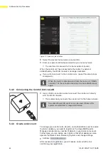
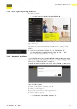
Страница 57: ...ta is to be found on a label on your WLAN module X Enter the serial number and the WLAN password Z The WLAN connection to the control unit is executed as a point to point connection 5 2 3 Starting the...

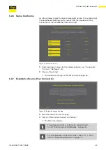
Страница 58: ...lds X Click on Next step Z The window for naming the control unit pops up 5 2 5 Name the Control Unit Use the following letters numbers and special characters to name the control unit or the rooms Let...

Страница 59: ...es for the indicated rooms e g Living room Kitchen Bathroom etc X Click on Next step Z The window for the type of WLAN connection pops up 5 2 7 Establish a Peer to Peer Connection Figure 26 Select the...

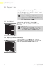
Страница 60: ...tandable information on operating states and control parameters 6 1 Operating Software on page 72 5 3 1 Cooling Mode 6 1 8 Rooms Additional Settings Menu on page 78 Cooling mode is indicated by the ic...

Страница 61: ...n via Software You can operate several control units simultaneously via Internet connection also when you re away from home For this the control units in question must be connected to the router eithe...

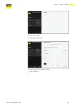
Страница 62: ...dule This data is to be found on a label on your WLAN module X Select the network serial number of the WLAN module is indicated and enter the WLAN password Z The WLAN connection to the control unit is...

Страница 63: ...63 IM HC 599871 0321 RABS Software Set Up Procedures Figure 29 Central settings X Select the control unit Figure 30 Sub menu for the selected control unit X Click on WLAN...

Страница 64: ...2 Connecting the Control Unit via LAN X Use an RJ45 connection cable to connect the control unit directly with the WLAN module Z This automatically connects the control unit to the home network So ca...

Страница 65: ...tration X Enter your personal data Use the following letters numbers and special characters Letters a z A Z Numbers 0 9 Special characters After you have finished registration you ll receive an email...

Страница 66: ...ure 34 Log in window X Enter your email and password and click on Login After successful login you can go to the device management of your account Since no devices have been connected with your accoun...

Страница 67: ...AN module X Enter the serial number and password of the WLAN module X Use the Object selection menu to select an existing object or generate a new object X Press Add to confirm your entry Z The contro...

Страница 68: ...information are listed under the object Assigning a control unit to another object X Click on Assign in the line of the control unit Z A change field opens X Assign the control unit to another object...

Страница 69: ...tion and setting see 6 1 1 Start Screen of Operating Software on page 72 5 4 6 Managing Members In the Members area you can add additional users for the control of the objects and assign authorization...

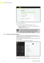
Страница 70: ...has not been assigned administrator rights he or she cannot effect any changes or deletions 5 4 7 Performing Software Updates In regular intervals you will automatically be informed of software update...

Страница 71: ...date Version Figure 42 Installation dialogue for available control units X Click on Install Z The installation of the software update starts Carry out all indicated software updates After installation...

Страница 72: ...ing Software 6 1 1 Start Screen of Operating Software Figure 43 Start menu 1 Rooms menu 1st and 2nd floor with room names 2 Go away mode menu 3 Operating mode menu 4 Central settings menu The Start me...

Страница 73: ...ettings Menu on page 78 Allow the cooling function Prioritized heating Floor temperature retention Profile activated 2 Leaving home mode menu Activate leaving home mode 6 1 9 Leaving Home Mode Menu on...

Страница 74: ...ault Menu on page 90 Update Version 6 1 23 Central Settings Update and Version Menu on page 90 Imprint Support A 6 1 24 Central Settings Imprint and Support Menu on page 91 System time A 6 1 25 Centra...

Страница 75: ...o the thermostat 4 3 Method 2 Zone Control via Thermostat on page 46 6 1 5 Rooms Menu Change Heating Profile Figure 46 Heating profile menu X Change heating profile Room temperatures can be set for 6...

Страница 76: ...all weekdays opens X Select the days to which you want to paste the profile and click on Copy 6 1 6 Copy Rooms Heating Profile Menu Figure 48 Copy the heating profile You can copy the heating profile...

Страница 77: ...X Push the slide to the desired temperature Minimum temperature Temperature below which no manual setting at the thermostat is possible Maximum temperature Temperature above which no manual setting a...

Страница 78: ...temperature of this room has fallen at least 2 k below the target temperature Floor temperature retention The effect of external heat sources e g insulation causes the heating circuits to close when...

Страница 79: ...erature in such a way that the set target value is reached when you return home If you do not set a return time or disable the function the leaving home mode will continue until you disable it via thi...

Страница 80: ...activated Time and Temperature Saving mode for all rooms temperature reduced by 3 C Standby mode the system is switched off anti freeze is enabled no settings can be made Cooling mode activated contr...

Страница 81: ...Information on the selected operating mode is indicated directly in the menu or when you move the cursor over the question mark icon 6 1 11 Central Settings WLAN Menu Figure 54 Indication of WLAN netw...

Страница 82: ...it Change settings Push the slide to Sort Change the indication sequence Edit X Set the slide control to Edit X Click on the desired control unit Z The Overview control units is indicated Sort X Set t...

Страница 83: ...number of the control unit cannot be changed Software version Software version of the control unit used cannot be changed Supply temperature Current supply temperature cannot be changed WLAN X Click...

Страница 84: ...and Renaming Rooms Figure 57 Room names X Click on Sort The following settings are possible Changing room names Change the indication sequence of the rooms use drag drop to move the room to the desir...

Страница 85: ...t offset of an powerhead indication 1 you increase the heat level of the heating circuit Use this function for heating circuits in the area of heavily insulating floor coverings rugs wooden floorboard...

Страница 86: ...Click Activate point to point mode to establish a direct connection between the end device and the control unit Z In this mode the control unit is not connected to a router To connect the control unit...

Страница 87: ...unit X Select F Fahrenheit or C Celsius Date format X Select dd mm yyyy or mm dd yyyy Time format X Select 12 or 24 hours Time zone X Select timezone Summer winter changeover The automatic time chang...

Страница 88: ...g while in heating mode and from falling below dew point in cooling mode X Set the slide for the minimum and maximum supply temperature to the desired temperature 6 1 20 Central Settings Analyze Suppl...

Страница 89: ...t your settings from unauthorized access This function is available in point to point mode only X Switch the modification protection on X Enter the user name and password X Click on Save Comply with t...

Страница 90: ...registered during the auto check of the system 7 1 Control Unit on page 93 6 1 23 Central Settings Update and Version Menu Figure 66 Updates Indication of the software versions installed on the contr...

Страница 91: ...tings Imprint and Support Menu Figure 67 Imprint Indication of the Viega service contact information X Click the pen icon to change the contact data for technical support Figure 68 Change address deta...

Страница 92: ...69 System time Indication of the current system time in dd mm yy hh mm format If the end device shows an incorrect time check the time settings and the time zone The control units are equipped with a...

Страница 93: ...shes red Potential causes Corrective actions 3 x Radio connection to the thermostat is interrupted Check signal strength Check the location of the thermostat 4 3 5 Checking the Radio Connection on pag...

Страница 94: ...ng commissioning or defective Disconnect control unit from the mains remove bus cable connect control unit with the mains do a reset disconnect control unit from the mains connect all cables connect c...

Страница 95: ...ns Illuminates green once followed by yellow flashing Power level enabled No radio connection to the thermostat Check whether the thermostat is logged in See control unit Emits red light Control unit...

Страница 96: ...component refer to the respective sections in this instruction manual 8 3 1 Replacing the Powerhead X Pull the mains plug of the control unit switch mains voltage off X Pull off the circuit hub of the...

Страница 97: ...he defective supply temperature sensor X Mount the new supply temperature sensor and plug in X Reconnect the mains plug to the control unit X Check the humidity sensor for proper function fault indica...

Страница 98: ...verview INFO The serial number of the new control unit is indicated for the object but without a name for the control unit X Enter the name of the control unit and the room name INFO The Room overview...

Страница 99: ...nit A and WLAN module 1 is still stored on the server For security reasons the server therefore does not allow the addition of a new device e g a combination of control unit A with WLAN module 2 On th...

Страница 100: ...een control unit A and WLAN module 1 is still stored on the server For security reasons the server therefore does not allow the addition of a new device i e of control unit A linked to the new tenant...

Страница 101: ...tools sold by Viega under normal conditions of use shall be free from failure caused by manufacturing defects for a period of two 2 years from date of sale Under this limited warranty you only have a...

Страница 102: ...for repair and replacement of the product covered by this warranty VIEGA SHALL NOT BE LIABLE FOR CONSEQUENTIAL ECONOMIC LOSS DAMAGES UNDER ANY LEGAL THEORY AND WHETHER ASSERTED BY DIRECT ACTION FOR C...

Страница 103: ......

Страница 104: ...ny questions regarding function or operation of RABS please contact Email Techsupport viega us Phone 877 843 4262 Ext 350 www viega us Viega RABS Portal www rabs viega us Peer to peer connection to a...

Отзывы: