Instruc
tion manual - English - EN
7
MNVCMVXTBCAM_2121_EN
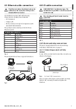
4.3 Ethernet cable connection
The Ethernet cable shield must always be
earthed via the connector. Always use a
shielded RJ45 connector.
Use of Ethernet cables with the following
characteristics is highly recommended:
• STP (shielded)
• Category 5E
• RJ45 connector (crimped in compliance with
standard TIA/EIA-568-B)
The product can be directly connected to an
Ethernet switch.
ETHERNET CABLE CONNECTION
Pin number
Core colour
1
Orange-White
2
Orange
3
Green-White
4
Blue
5
Blue-White
6
Green
7
Brown-White
8
Brown
Tab.
4
The example below shows a typical installation.
Switch
Personal
Computer
Fig.
1
4.4 I/O cable connection
CAUTION! TNV-1 installation type. The
installation is type TNV-1, do not connect it
to SELV circuits.
The shielding of the I/O cable must be
grounded.
I/O CABLE CONNECTION
Colour
Function
White
RS-485 A (+)
Yellow
RS-485 B (-)
Pink
Relay 1, Terminal A
Blue
Relay 1, Terminal B
Brown
Alarm/Digital input
Green
GND/Common alarm
Grey
Reset
Tab.
5
4.4.1 Alarm and relay connections
The unit is equipped with the alarms and relays
indicated in the table (Tab. 5, page 7).
4.4.1.1 Connecting an alarm with dry
contact
In case of free contact alarm make the connection as
shown in the figure.
AL
COM
Dry contact
Fig.
2
AL: Alarm. COM: Common alarm.
Clean contact of the alarm can be set NO (normally
open) or NC (normally closed) using the web
interface.
Содержание MAXIMUS MVXT
Страница 2: ......
Страница 87: ...KO 한국어 지침 설명서 한국어 MAXIMUS MVXT 컴팩트 디자인의 고사양 방폭형 열 카메라 핸드북을 B ...
Страница 101: ......


