background image

Videoswitch R-Series 

N

VR Quick Guide


11 

Vi-R5516


No. 

Name 

Function Description 

Status 

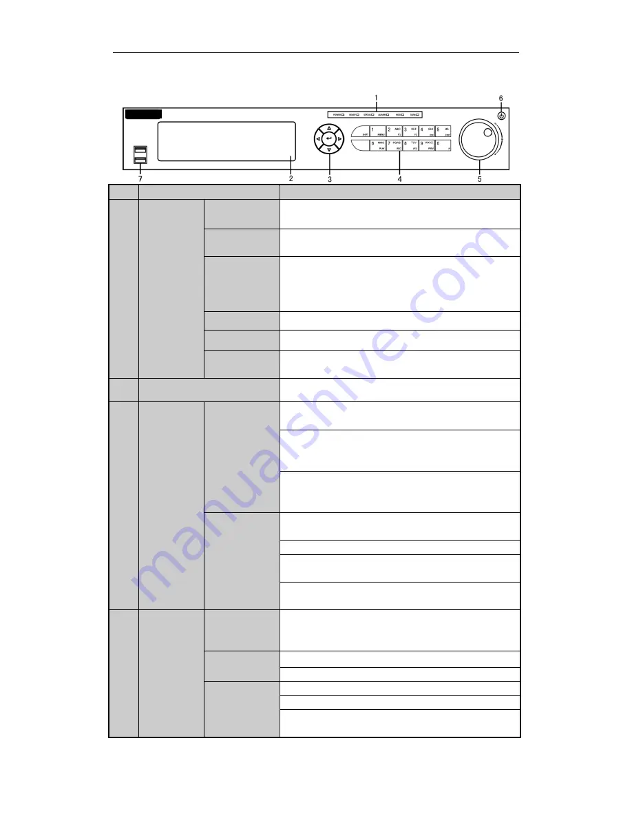
Indicators 

POWER 

Turns green when NVR is powered up. 

READY 

The LED is green when the device is running normally. 

STATUS 

The light is green when the IR remote control is enabled; 

The light is red when the function of the composite keys (SHIFT) 

are used; 

The light is out when none of the above condition is met. 

ALARM 

The light is red when there is an alarm occurring. 

HDD 

Blinks red when HDD is reading/writing. 

Tx/Rx 

Blinks green when network connection is functioning normally. 

DVD-R/W 

Slot for DVD-R/W.


Control 

Buttons 

DIRECTION 

In menu mode, the direction buttons are used to navigate between 

different fields and items and select setting parameters. 

In playback mode, the Up and Down buttons are used to speed up 

and slow down record playing, and the Left and Right buttons are 

used to move the recording 30s forwards or backwards. 

In the image setting interface, the up and down button can adjust 

the level bar of the image parameters. 

In live view mode, these buttons can be used to switch channels. 

ENTER 

The  Enter  button  is  used  to  confirm  selection  in  menu  mode;  or 

used to check checkbox fields and ON/OFF switch. 

In playback mode, it can be used to play or pause the video. 

In single-frame play mode, pressing the Enter button will play the 

video by a single frame. 

In auto sequence view mode, the buttons can be used to pause or 

resume auto sequence. 

Composite 

Keys 

SHIFT 

Switch  between  the  numeric  or  letter  input  and  functions  of  the 

composite  keys.  (Input  letter  or  numbers  when  the  light  is  out; 

Realize functions when the light is red.) 

1/MENU 

Enter numeral “1”; 

Access the main menu interface. 

2/ABC/F1 

Enter numeral “2”; 
Enter letters “ABC”; 

The F1 button when used in a list field will select all items in the 

list. 

Front Panel


Содержание Vi-R5216L

Страница 1: ...al Vi R5216L Vi R5516 Vi R5532 Document Reference Date Bdr604a pdf 01 06 15 Videoswitch Telephone 01252 851510 Unit 15 Redfields Industrial Park Fax 01252 851296 Redfields Lane Church Crookham Email s...

Страница 2: ...108 EC the RoHS Directive 2011 65 EU 2012 19 EU WEEE directive Products marked with this symbol cannot be disposed of as unsorted municipal waste in the European Union For proper recycling return thi...

Страница 3: ...ventilated and dust free area 3 Ensure environmental conditions meet factory specifications 4 Install a manufacturer recommended HDD NVR Installation During the installation of the NVR 1 Use brackets...

Страница 4: ...s NVR Quick Guide 6 1 Remove the cover from the NVR by unfastening the screws on the rear and side panel 2 Connect one end of the data cable to the motherboard of NVR and the other end to the HDD Hard...

Страница 5: ...Videoswitch R Series NVR Quick Guide 7 4 Place the HDD on the bottom of the device and then fasten the screws on the bottom to fix the HDD 3 Connect the power cable to the HDD...

Страница 6: ...slow down record playing and the Left and Right buttons are used to move the recording 30s forwards or backwards In the image setting interface the up and down button can adjust the level bar of the i...

Страница 7: ...eral 7 Enter letters PQRS Open the manual record interface 8 TUV PTZ Enter numeral 8 Enter letters TUV Access PTZ control interface 9 WXYZ PRE V Enter numeral 9 Enter letters WXYZ Multi channel displa...

Страница 8: ...tions when the light is red 4 Composite Keys SHIFT Switch between the numeric or letter input and functions of the composite keys Input letter or numbers when the light is out Realize functions when t...

Страница 9: ...navigate between different fields and items and select setting parameters In playback mode the Up and Down buttons are used to speed up and slow down record playing and the Left and Right buttons are...

Страница 10: ...Videoswitch R Series NVR Quick Guide 15 Rear Panel Vi R5216 Vi R5516...

Страница 11: ...fely To connect an AC load jumpers should be left open you must remove the jumper on the motherboard in the NVR Use an external relay for safety as shown in the figure above There are 4 jumpers JP1 JP...

Страница 12: ...the KB terminal block 2 Unfasten stop screws from the KB D D pluggable block insert signal cables into slots and fasten stop screws Ensure signal cables are in tight 3 Connect Ta on controller to D o...

Страница 13: ...on 5MP 3MP 1080P UXGA 720P VGA 4CIF DCIF 2CIF CIF QCIF Capability 10 ch 720P 5 ch 1080P 16 ch 720P 8 ch 1080P 16 ch 720P 8 ch 1080P Hard disk SATA 4 SATA interfaces for 2 HDDs 1 DVD R W default or 4HD...

Страница 14: ...ch 720P 5 ch 1080P 16 ch 720P 8 ch 1080P Hard disk SATA 2 SATA interfaces Capacity Up to 4TB capacity for each HDD External interface Network interface 1 RJ 45 10 100 1000 Mbps self adaptive Ethernet...

Страница 15: ...Storage Used 96K 42M 128K 56M 160K 70M 192K 84M 224K 98M 256K 112M 320K 140M 384K 168M 448K 196M 512K 225M 640K 281M 768K 337M 896K 393M 1024K 450M 1280K 562M 1536K 675M 1792K 787M 2048K 900M 4096K 1...

Страница 16: ...mended to change the initial password right after the first login to avoid safety problem You may use one of the following listed web browsers Internet Explorer 6 0 Internet Explorer 7 0 Internet Expl...

Страница 17: ...clicking the mouse 2 Double click a camera from the device list to start the live view 3 You can click the button on the toolbar to start the live view of all cameras on the device list Refer to the...

Страница 18: ...nd Time Up to 8 segments can be configured and each segment cannot be overlapped 2 Select a Record Type The record type can be Continuous Motion Alarm Motion Alarm Motion Alarm and VCA 3 Check the che...

Страница 19: ...ations are supported 4 Time Line Displays the time bar and the records marked with different colors 5 Playback Status Displays the playback status including channel number and playback speed 6 Calenda...

Страница 20: ...e steps 2 4 Transcoded Playback Purpose To save the bandwidth cost the transcoded playback can be adopted Steps 1 Make sure the playback of current channel is stopped 2 Move the mouse to the icon and...

Страница 21: ...Guide 34 4 The matched log files will be displayed on the list Up to 2000 log files can be found each time and 100 log files can be displayed on each page You can click the button to save the searche...

Страница 22: ...Videoswitch R Series NVR Quick Guide 35 Menu Operation Menu Structure The menu structure of the R Series NVR...

Страница 23: ...enu Menu Shutdown 2 Select the Shutdown button 3 Click the Yes button Live View Some icons are provided on screen in Live View mode to indicate different camera status These icons include Live View Ic...

Страница 24: ...e One couch Adding button to add all the online IP cameras The added camera is marked in white while the camera has not been added is marked in yellow Explanation of the icons Icon Explanation Icon Ex...

Страница 25: ...u can edit the IP address protocol management port and other information of the IP camera to be added 3 Click Add to add the camera 4 For the encoders with multiple channels only check the checkbox of...

Страница 26: ...manual records enabled are canceled Instant Recording On the live view window of each channel there is a quick setting toolbar which shows on the bottom of the window when you click on it Click the ic...

Страница 27: ...creen live view record files of the selected channel will be played back Pressing numerical buttons will switch playback to related channels during playback process Playback Play back the record files...

Страница 28: ...o switch playback to another channel or execute simultaneous playback of multiple channels Backup Recorded files can be backed up to various devices such as USB flash drives USB HDDs or a DVD writer S...

Страница 29: ...Videoswitch R Series NVR Quick Guide 42 3 Check backup result Choose the record file in Export interface and click button to check it...

Отзывы: