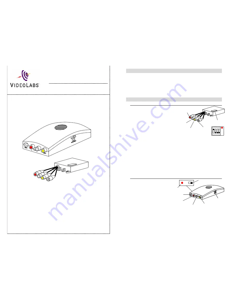
Channel
Selector
Video Connector
Left (White)
Audio Connector
Right (Red)
Audio
Connector
ON OFF
12V Power
Connector
Power Indicator
Power Switch
The VideoLabs’ Wireless Audio/Video System transmits live video
through the air instead of hard wires, allowing greater flexibility and
positioning of all VideoLabs cameras. Cameras can now be used in any
location without running a video cable from the camera to the monitor.
The wireless connection can extend over 700 feet.
In the Box:
The following items are included in the VideoLabs Wireless
Audio/Video System
•
Transmitter
•
Receiver
•
2 power supplies
•
Y – power cable
•
S-Video(M) to Composite(M) adapter cable (pigtail adapter)
Setup:
Transmitter
The camera outputs are
connected to the transmitter
inputs.
1.
Connect the audio output s
of the camera to the left
(white) and right (red)
audio inputs of the
transmitter. If there is only
one audio output on the
camera, connect it to either
audio input.
2.
Use the included pigtail adapter to connect the s-video output to the Video
input of the transmitter. If your camera does not have a female s-video
jack, use the pigtail adaptor included with your camera, or call VideoLabs
customer service to buy a compact connection cable.
3.
Lift the red plastic cover off the channel dip switches – put dip switch 1 in
the on position – put 2, 3, and 4 in the off position.
4.
Replace the red plastic cover.
5.
Plug the power supply into a wall outlet.
6.
Plug the other end of the power supply into the female end of the Y power
cable.
7.
Connect one of the Y cable male ends to the 12V power connector on the
transmitter, and the other to the 12V power connector on the camera.
Receiver
The receiver outputs are
connected to the monitor or
A/V equipment inputs.
1.
Connect the left and
right audio outputs of
the receiver to the left
and right audio inputs
of the monitor. If there
is only one audio
output on the camera,
connect the same (left
or right) output that was used in the transmitter setup.
2.
Connect the video output of the receiver to the video input of the monitor.
3.
Set the channel selector to 1.
4.
Plug the power supply into a wall outlet.
5.
Plug the other end of the power supply into the 12V power connector.
6.
Switch the power to the ON position.
Channel Dip
Switches
Video
Connector
Left Audio
Connector
Right Audio
Connector
12V Power
Connector
ON
1 2 3 4
Wireless A/V
2.4 GHz Wireless
Transmitter and Receiver System
Installation & User Guide


