4
3. Installation
3.1 General
●
Mount v ertically on a non-f lammable surf ace, with the power
terminals f acing downwards.
● Mount close to the battery , but nev er directly abov e the battery
(in order to prev ent damage due to gassing of the battery ).
● Grounding:
the heatsink of the controller should be connected
to the grounding point.
Tr models
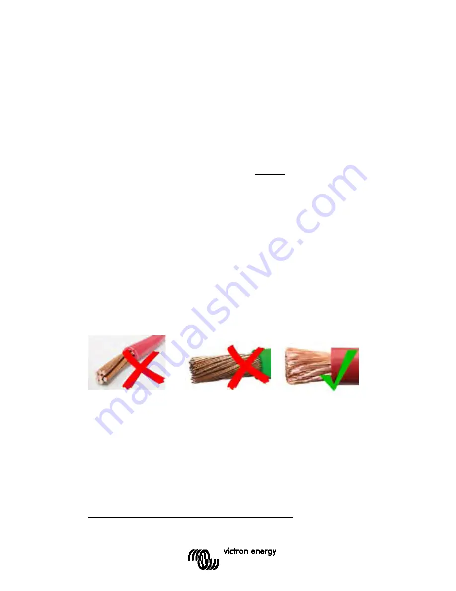
: use f lexible multistranded copper cable f or the battery
and PV connections (Tr models).
MC4 models
: sev eral splitter pairs will be needed to parallel the
strings of solar panels.
The maximum diameter of the indiv idual strands is
0,4 mm/0,125 mm² (0.016 inch/AWG26).
A 25 mm² cable, f or example, should hav e at least 196 strands
(class 5 or higher stranding according to VDE 0295, IEC 60228
and BS6360). Also known as H07V-K cable.
An AWG2 gauge cable should hav e at least 259/26 stranding
(259 strands of AWG26).
In case of thicker strands the contact area will be too small and
the resulting high contact resistance will cause sev ere
ov erheating, ev entually resulting in f ire.
3.2 PV configuration
●
The controllers will operate only if the PV v oltage exceeds
battery v oltage (Vbat).
●
PV v oltage must exceed Vbat + 5V f or the controller to start.
Thereaf ter minimum PV v oltage is Vbat + 1V.
●
Maximum open circuit PV v oltage: 150V.
The controllers can be used with any PV conf iguration that
satisf ies the three abov e mentioned conditions.
For example:
24V battery and mono- or poly cristalline panels


