Victaulic 751 FireLock Series Скачать руководство пользователя страница 9


Series 751 FireLock® Alarm Check Valve


8


IMPORTANT INSTALLATION 


INFORMATION


1.


For proper operation and approval, the Series 751 Alarm Check 

Valve must be installed in accordance with the specific trim diagrams 
included in the shipment. 


NOTE:


 Victaulic provides specific trim dia-


grams for vertical and horizontal installations.


2.


Before installing the Series 751 Alarm Check Valve, flush the 


water supply piping thoroughly to remove all foreign material.


3.


Series 751 Alarm Check Valves 


MUST NOT


 be located in an area 

where the valve can be exposed to freezing temperatures. In addition, 
the Series 751 Alarm Check Valve 


MUST NOT


 be located in an area 


where physical damage may occur.


4.


It is the owner’s responsibility to confirm material compatibility of 

the Series 751 Alarm Check Valve, trim, and associated accessories 


when a corrosive environment or contaminated water is present.


5.


The Victaulic Series 752 Retard Chamber should be installed in 

variable pressure installations. 


NOTE:


 Victaulic provides specific trim 


drawings for installations that involve a Series 752 Retard Chamber.


6.


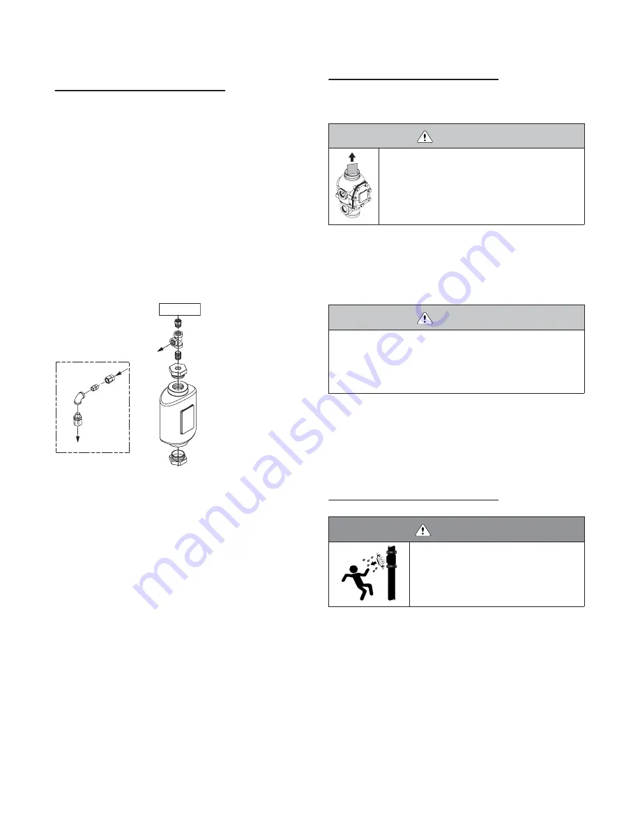
The Series 752V Retard Vent Kit is required any time an air break 

is needed above the retard chamber. In addition, the Series 752V 
Retard Vent Kit is required if multiple valves are tied into one water 
motor alarm and a check valve isolates each line. Refer to the drawing 


above.


7.


Series 751 Alarm Check Valves can be installed in the vertical 

position with the arrow on the body pointing upward. The arrow on the 


swing check valve in the bypass line must point upward.


8.


When installed horizontally, the cover plate must face up-

ward. The arrow on the swing check valve in the bypass line must 


match the direction of the water flow.


9.


When the Series 751 Alarm Check Valve is used with a water 

motor alarm, it is recommended that the valve contain an uninterrupted, 
low-pressure alarm that is installed on the piston charge line down-


stream of the check valve.


VALVE/TRIM INSTALLATION


1.


Make sure trim drawings match system requirements. Refer to 


page 7 for the listing.


2.


Remove all plastic caps and foam spacers from the valve.


3.


Apply a small amount of pipe joint compound or Teflon* tape to 

the external threads of all threaded pipe connections. DO NOT get any 
tape, compound, or other foreign material in the valve body, pipe nip-
ples, or valve openings.

4.

Install the valve, trim, and accessories per the trim drawing.

* Teflon is a registered trademark of the Dupont Company

HYDROSTATIC TESTING

The Victaulic Series 751 Alarm Valve is UL Listed and FM Approved for 
a maximum working pressure of 300 psi (2065 kPa) for 1

1

/

2

 - 6-inch (40 

– 150-mm) sizes and 225 psi (1551 kPa) for the 8-inch (200-mm) size. 
The valve is factory tested to 600 psi (4135 kPa) for 1

1

/

2

 - 6-inch (40 – 

150-mm) sizes and 500 psi (3447 kPa) for the 8-inch (200-mm) size. The 
valve can be hydrostatically tested against the clapper at 200 psi (1380 
kPa) or 50 psi (345 kPa) above the normal water supply pressure (2-
hour limited time period) for acceptance by the authority having 
jurisdiction.

Optional Series 752V

Retard Vent Kit

To Water Motor

Alarm or Optional

Restrictor

Optional Pressure

Switch

Pipe to

Open Drain

CAUTION

• Make sure the foam spacer is removed from inside 

the valve body before attempting to install the valve.

Failure to follow this instruction could cause improper 
valve operation, resulting in personal injury and/or 
property damage.

CAUTION

• Make sure no foreign material gets into the valve body, pipe nip-

ples, or valve openings.

• If using any material other than Teflon tape, use extra caution so 

that no material gets into the trim.

Failure to follow these instructions could cause improper valve 
operation and/or property damage.

WARNING

• If air testing is required, DO NOT exceed 50-

psi (345-kPa) air pressure.

Failure to follow this instruction could result in 
serious personal injury and/or property dam-
age.

Содержание 751 FireLock Series

Страница 1: ...ctions before attempting to install any Victaulic piping products Wear safety glasses hardhat and foot protection Save this installation maintenance and testing manual for future reference If you need...

Страница 2: ...apper Seal for 4 6 inch 100 150 mm Size Valves 16 Removing and Replacing the Clapper Assembly All Sizes 17 Installing the Cover Plate Gasket and Cover Plate 18 Troubleshooting Series 751 Alarm Check V...

Страница 3: ...d spring loaded components i e clapper assembly 8 Keep work areas clean Cluttered areas benches and slippery floors can create hazardous working conditions 9 PROTECT THE SYSTEM FROM FREEZING CONDITION...

Страница 4: ...3 286 305 229 127 127 16 0 23 6 4 4 500 15 03 23 50 29 00 14 00 13 50 15 00 10 00 5 80 5 80 49 0 80 0 100 114 3 381 76 597 737 356 343 381 254 147 147 22 2 36 3 6 6 625 16 00 24 00 30 11 17 28 14 25 1...

Страница 5: ...ssure Gauge 0 300 psi 0 2068 kPa 11 Series 705W Butterfly Valve Optional 5 Alarm Line Ball Valve NO 12 Style 005 FireLock Rigid Coupling Optional 6 Alarm Test Line Ball Valve NC 13 PS10 1 or PS10 2 Al...

Страница 6: ...System s Main Drain Valve 3 Swing Check Valve 9 Series 760 Water Motor Alarm Optional 4 System Pressure Gauge 0 300 psi 0 2068 kPa 10 Series 705W Butterfly Valve Optional 5 Alarm Line Ball Valve NO 11...

Страница 7: ...9 Clapper Spring 2 Clapper 10 Spacers Qty 2 3 Clapper Seal 11 Clapper Shaft 4 Seal Ring 12 Clapper Shaft Retaining Plug Qty 2 5 Seal Washer Not Used on 1 2 40 50 mm Valves 13 Cover Plate 6 Seal Retain...

Страница 8: ...1 2 2 875 Z024751201 Z024751251 165 1 mm 6 500 Z060751201 Z060751251 65 73 0 165 1 76 1 mm 3 000 Z024751201 Z024751251 8 8 625 Z080751201 Z080751251 76 1 200 219 1 3 3 500 Z024751201 Z024751251 80 88...

Страница 9: ...ntain an uninterrupted low pressure alarm that is installed on the piston charge line down stream of the check valve VALVE TRIM INSTALLATION 1 Make sure trim drawings match system requirements Refer t...

Страница 10: ...water supply pressure gauge 8 Open the alarm line ball valve 9 Confirm that all valves are in their normal operating positions refer to table below 10 Notify the authority having jurisdiction remote...

Страница 11: ...ea that the main drain test will be per formed 2 Confirm that sufficient drainage is in place for a full flow drain test 3 Record the water supply s pressure and the system s water pres sure 4 Close t...

Страница 12: ...he proper water supply pressure 10 Open the alarm line ball valve 11 Confirm that all valves are in their normal operating positions refer to table below 12 Notify the authority having jurisdiction re...

Страница 13: ...over plate bolts along with the cover plate and cover plate gasket WARNING Depressurize and drain the piping system before attempting to remove the cover plate from the alarm check valve Failure to fo...

Страница 14: ...NOT USE SOLVENTS OR ABRASIVES 6 Inspect the clapper for freedom of movement and physical dam age Replace any damaged or worn parts by following the applicable instructions in the Maintenance section...

Страница 15: ...ture that is under the seal washer and on the clapper seal WARNING Depressurize and drain the piping system before attempting to remove the cover plate from the alarm check valve Failure to follow th...

Страница 16: ...clapper 9 Install the clapper seal into the clapper carefully Make sure the seal ring snaps into the clapper completely 10 Place the seal retaining ring onto the seal washer of the clapper seal 11 Ins...

Страница 17: ...taulic supplied solid clapper seal 5 Make sure contaminants dirt and mineral deposits are removed from the clapper 6 Install the solid clapper seal into the clapper NOTE Make sure the sealing lip is p...

Страница 18: ...g will drop out of position Keep the spacers and clapper spring for re installation 3 Remove the clapper from the valve body 4 Place the new clapper assembly onto the valve body seat ring Make sure th...

Страница 19: ...stem in Service section starting on page 9 Installing the Cover Plate Gasket and Cover Plate 1 Verify that the cover plate gasket is in good condition If the gasket is torn or worn replace it with a n...

Страница 20: ...ting on page 9 CAUTION DO NOT over tighten the cover bolts Failure to follow this instruction could cause damage to the cover plate gasket resulting in valve leakage Required Cover Bolt Torque Valve S...

Страница 21: ...mage Make sure no debris is present on the clapper seal and seat Make sure there is no vacuum in the alarm line If a vacuum is present in the alarm line install the Series 752V Retard Vent Kit or crea...

Страница 22: ...84 7444 Fax 905 884 9774 Phone 32 9 381 15 00 Fax 32 9 380 44 38 e mail viccanada victaulic com e mail viceuro victaulic be VICTAULIC AMERICA LATINA VICTAULIC ASIA PACIFIC P O Box 31 Easton PA USA 180...

Отзывы: