


Design Guide & Applications Manual
For VI-200 and VI-J00 Family DC-DC Converters and Configurable Power Supplies
VI-200 and VI-J00 Family Design Guide
Rev 3.4
vicorpower.com
Page 17 of 97
Apps. Eng. 800 927.9474
800 735.6200
cost incurred by the addition of at least one redundant
converter or supply.
Incidentally, most applications today that require fault
tolerance or redundancy also require Hot-Swap capability
to ensure continuous system operation. Hot-swappable
cards must be designed so the operator won’t come in
contact with dangerous potentials and currents.
It’s also essential that when a module fails, the failure is
detected and identified by an alarm or notice to provide
service. A Hot-Swap system must ensure that during
swap-out, there is minimal disturbance of the power bus.
Specifically, the affected voltage bus must not drop
enough to cause errors in the system, either on the input
bus or the output bus.
A power-supply failure can cripple an entire system, so the
addition of a redundant converter or supply is often
justified by the need to keep the system operating.
Adding an extra module (N+1) to a group of paralleled
modules will significantly increase reliability with only a
modest increase in cost.
The implementation of redundant converters is
determined in part by the available space and cost
requirements. For example, two 200 W full-size modules
could be used to provide a 400 W output with an
additional 200 W module for 2+1 redundancy (a total of
600 W in a volume of about 16.5 in
3
).
Alternatively, four 100 W half-size modules might be used
with a fifth 100 W module to provide 4+1 redundancy (a
total of 500 W and 14 in
3
). Although the second solution
uses less space, it increases the accumulated failure rate
because it employs more converters, more ORing diodes,
more monitoring circuitry, and more assembly.
ORing diodes may be inserted in series with the output
of each module in an N+1 array to provide output fault
tolerance. (Figure 8–2) They’re important in a redundant
power system to maintain fault isolation. Without them,
a short-circuit failure in the output of one converter could
bring down the entire array.
But ORing diodes add losses to the power system,
reducing overall efficiency and decreasing reliability. To
ameliorate the negative effect on efficiency, ORing diodes
should run hot, thereby reducing forward voltage drop
and increasing efficiency. Reverse leakage current will be
an issue only if the output of a converter shorts and the
diode is reverse biased. This is an important consideration
with regard to operating temperature.
8. Using Boosters and Parallel Arrays
INPUT
LOAD
+ Sense
Trim
–Sense
GATE
IN
–IN
Zero-Current-
Switching Driver
+OUT
GATE
OUT
+IN
–OUT
+Sense
Trim
–Sense
–IN
Zero-Current-
Switching Booster
+OUT
+IN
–OUT
+Sense
Trim
–Sense
–IN
Zero-Current-
Switching Booster
+OUT
+IN
–OUT
+VIN
-VIN
GATE
IN
GATE
OUT
GATE
IN
GATE
OUT
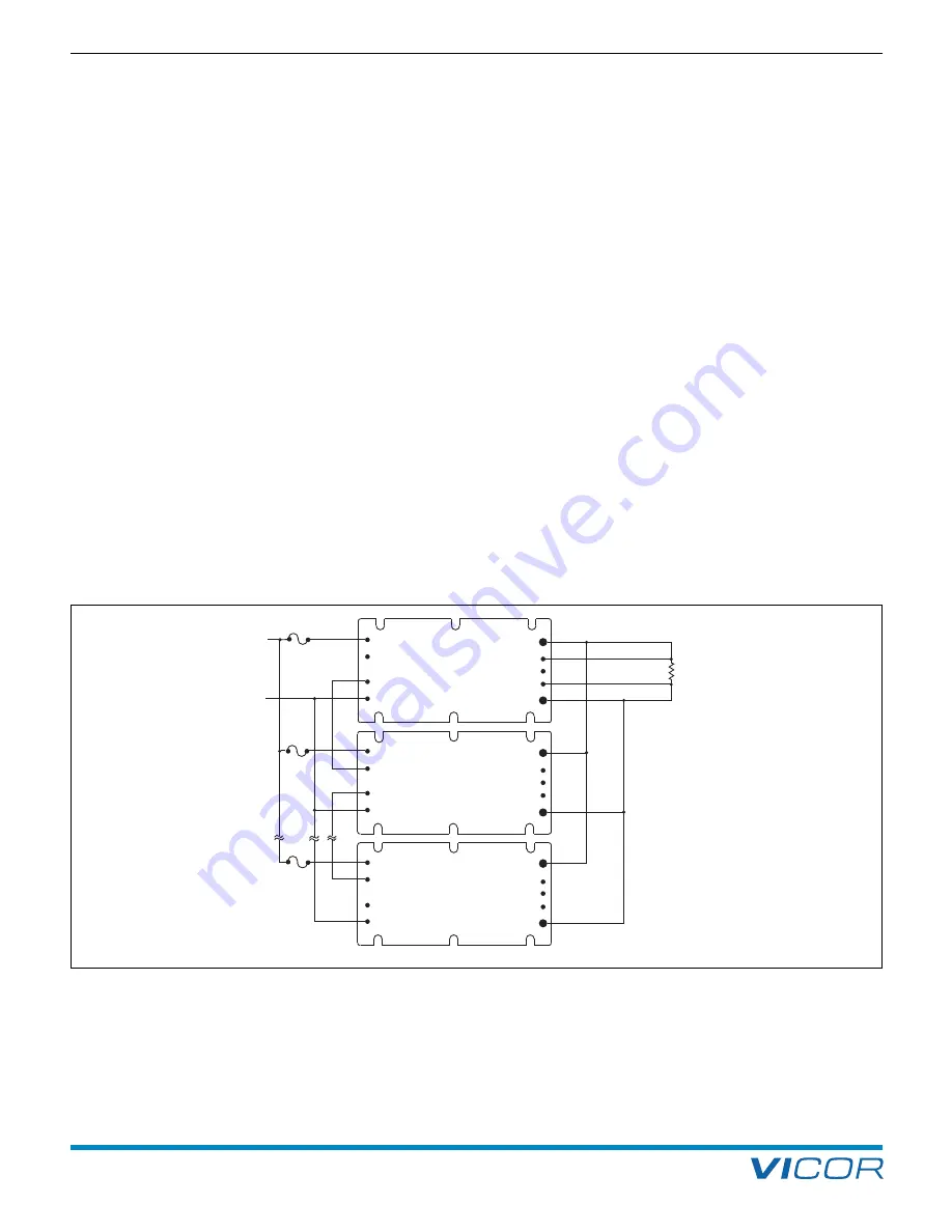
Figure 8–3
— Most converters can use the Driver / Booster array to increase output power. Driver / Booster arrays usually contain one
intelligent module or Driver, and one or more power-train-only modules or Boosters.
Содержание VI-200 Series
Страница 100: ......


