background image

8 | PIR Ready VTR7300 Series-Installation Guide 


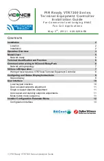
Wiring of local inputs to VTR73xxA Terminal Equipment Controller 


C

ONFIGURING AND 

S

TATUS 

D

ISPLAY 

I

NSTRUCTIONS


Status display 

The VTR73xxA Terminal Equipment Controller features a two-line, eight-character display. 
There is a low-level backlight that is always active and can only be seen at night. 


When left unattended, the Terminal Equipment Controller has an auto scrolling display 
that shows the status of the system. There is an option in the configuration menu to 
lockout the scrolling display and to only display the room temperature and conditional 
outdoor temperature to the user. With this option enabled, no local status of mode, 
occupancy and relative humidity is shown. 


Each item scrolls individually with the back lighting in low level mode. Pressing any key 
will cause the back light to come on to high level. When left unattended for 10 seconds 
after changes are made, the display will resume automatic status display scrolling. 


To activate the back light to high level, press any key on the front panel. The back light 
display will return to low level when the Terminal Equipment Controller is left unattended 
for 45 seconds. 


Sequence of auto-scroll status display: 

ROOM & 

HUMIDITY 

SYSTEM MODE 

SCHEDULE 

STATUS 

OUTDOOR 

TEMPERATURE 

ALARMS 

x.x °C or °F 
XX % RH 

Sys mode 
auto 

Occupied 
 

Outdoor 
x.x °C or °F 

Service 
 

If humidity display 
enabled 

Sys mode  
cool  

Stand-By 
 

Network value only 
 

Filter 
 

RoomTemp 
x.x °C or °F 

Sys mode 
heat 

Unoccup 
 

n/a 

Window 
 

If humidity display 
is not enabled 

Sys mode  
off 

Override 
 

n/a 

Low Batt 


VTR73xxA


Terminal Controller


13 


-


BI 1


14 


-


Scom


15 


-


BI 2


Local BI 1 Input by configuration:


-


None (monitoring only)


-


Remote motion detector: Motion NO or Motion NC 


 - Remote Night Setback: RemNSB 


Local BI 2 Input by configuration:


-


None (monitoring only)


-


Door contact: DoorDry


- Window contact Window: 


Содержание VTR7300 Series

Страница 1: ...rminal Equipment Controller 8 Configuring and Status Display Instructions 8 Status display 8 User Interface 10 Local keypad interface 10 Dual occupied setpoints adjustment 11 Single occupied setpoints...

Страница 2: ...radiation 5 Nothing should restrict vertical air circulation to the Terminal Equipment Controller Installation 1 Swing open the Terminal Equipment Controller PCB to the left by pressing the PCB lockin...

Страница 3: ...ed and wired for the following o Cooling only o Heating only o Cooling Heating with network or local auto changeover If replacing an existing Line Voltage FCU Thermostat label the wires before removal...

Страница 4: ...ic reheat model dependent The VC3xxxX Relay Pack supplies power to the wall VTR73xxA Terminal Equipment Controller The VTR73xxA Controller controls the VC3xxxX Relay Pack s via a simple communication...

Страница 5: ...5 PIR Ready VTR7300 Series Installation Guide MODEL CHART...

Страница 6: ...adapter o VCM7300T5000B Terminal Equipment Controller BACnet MS TP communication adapter TERMINAL IDENTIFICATION AND FUNCTION TERMINAL IDENTIFICATION ALL VTR73XXA5X00 X TERMINAL EQUIPMENT CONTROLLER T...

Страница 7: ...not necessary Connect only wires 1 Power Common and 2 Tx Rx Communication Network wiring topology VC3XXX LED OPERATION LED Time Status operation Condition of the Status LED Cause Solution 2 short bli...

Страница 8: ...ause the back light to come on to high level When left unattended for 10 seconds after changes are made the display will resume automatic status display scrolling To activate the back light to high le...

Страница 9: ...two alarms can appear at any given time The priority for the alarms are as follows Three status LED s on the Terminal Equipment Controller cover are used to indicate the status of the fan any speed a...

Страница 10: ...ailable as per sequence and menu selected Repetitively pressing the button will toggle between all the available modes Available menus are dependent on selected sequence of operation Is used to toggle...

Страница 11: ...lectric Reheat Off Heat 4 Electric Reheat Only Off Heat COOLING MODE HEATING MODE OFF MODE AUTO MODE Setpoint presented to user is the setpoint from the last action taken by the Terminal Equipment Con...

Страница 12: ...o is for Fan on demand On is On all the time Auto Auto speed fan mode is also offered in heating mode applications it will not have any effect on dehumidification It will strictly be used for noise co...

Страница 13: ...t unauthorized access to the configuration menu parameters A default value of 0 will not prompt a password or lock the access to the configuration menu Range is 0 to 1000 Com Addr Terminal Equipment C...

Страница 14: ...to 1000 Range 1 to 500 for centralized networked applications using a VWG or a Jace with the wireless stat driver Range 501 to 1000 is for stand alone applications where no VWG or Jace with the wirele...

Страница 15: ...ter to 255 means that every configuration parameters will be set manually BI 1 Binary input no 1 configuration Default value None None No function will be associated with the input Input can be used f...

Страница 16: ...configuration Default value None None No function will be associated with the input Input can be used for remote network monitoring COC NH Change over dry contact Normally Heat Used for hot cold wate...

Страница 17: ...alarm Contact closed Alarm displayed Service a backlit flashing Service alarm will be displayed on the Terminal Equipment Controller LCD screen when the input is energized It can be tied in to the AC...

Страница 18: ...ontrol for VC350xE models only Can be used with 2 4 pipes applications On VDC SSR electric heat 10 second pulsed time base modulation for VC340xE models only Can only be used with 2 pipes system only...

Страница 19: ...dHt to On to enable pulsed electric reheat applications with VR7300B E Fan Menu Mode button menu configuration Default is Menu 4 Menu displayed are dependent on model used and sequence of operation se...

Страница 20: ...Timer value Default 0 0 hours Time delay between the moment when the Terminal Equipment Controller toggles to stand by mode and the time when the Terminal Equipment Controller unoccupied mode and setp...

Страница 21: ...is 54 to 100 F 12 0 to 37 5 C Pband Proportional band setting Default is 3 Adjust the proportional band used by the Terminal Equipment Controller PI control loop Note that the default value of 3 0 F...

Страница 22: ...Dual Stp Dual Occupied Setpoints Adjustment AttchStp Single Occupied Setpoint Adjustment TOccTime Temporary occupancy time Default value 2 hours Temporary occupancy time with occupied mode setpoints...

Страница 23: ...H will represent a higher accuracy of control at the expense of wearing mechanical components faster Range is 3 4 5 6 7 8 C P H CoolNoNc Normally open or close device Default value NC Adjust the type...

Страница 24: ...bulk polymer type sensor Reading range from 10 90 R H non condensing 10 to 20 precision is 10 20 to 80 precision is 5 80 to 90 precision is 10 Less than 1 0 yearly typical drift 30 to 95 R H 12 0 to...

Страница 25: ...25 PIR Ready VTR7300 Series Installation Guide DRAWING DIMENSIONS Viconics Technologies Inc Tel Fax Toll free www viconics com...

Отзывы: