EN
ES
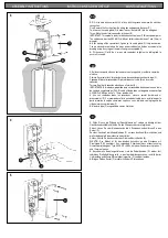
3. Fill in the hole with cement until it is flush with the ground and make the electrical
connection:
One: Remove the 4 screws from the wiring box and open up the cover (C).
Two: Loosen the cable gland (D) in order to insert the cable (B) into the wiring box.
Three: Make the electrical connection in the box (E).
IMPORTANT: This model is ready for direct connection to an IP 65-class power point.
The cable used must be H05 RN-F <HAR> or better rubber, between 7 and 12mm in
diameter.
4.
After making all the connections, tighten up the cable gland (D) firmly once more.
You are advised to seal where the mains power cable enters the box as shown in the
drawing, using the syringe of thermal silicon grease supplied (F).
5. Fit the cover (C) with the 4 screws and remember to tighten the cable gland to
ensure it is sealed.
D
3. Rellenar con pasta el hueco hasta enrasar con la superficie y realizar la conexión
eléctrica:
Primero: Desmontar los 4 tornillos de la caja de conexión para extraer la tapa (C).
Segundo: Aflojar el prensacables (D) para introducir el cable (B) en la caja de
conexión.
Tercero: Realizar la conexión eléctrica en el terminal (E).
IMPORTANTE: El modelo va preparado para ser conectado directamente a una toma
de corriente cumpliendo un IP 65. El cable utilizado debe ser de goma o superior tipo
H05 RN-F <HAR> de entre 7 y 12 mm. de diámetro.
4.
Una vez realizadas todas las conexiones, volver a apretar fuertemente el
prensacables (D). Se recomienda sellar la entrada del cable de su instalación por la
parte interior de la caja de conexiones, según se ve en el dibujo, con la jeringuilla de
silicona térmica suministrada (F).
5. Montar la tapa (C) asegurándola con los 4 tornillos.
3. Füllen Sie nun die Öffnung mit Spachtelmasse auf, sodass sie bündig mit der
Oberfläche abschließt und führen Sie den Stromanschluss wie folgt durch:
Erstens: Lösen Sie vom Klemmenkasten die 4 Schrauben und entfernen Sie den
Deckel (C).
Zweitens: Lockern Sie die Kabelklemmen (F), um dann das Kabel (B) einzuführen und
die Verbindung im Klemmenkasten herzustellen.
Drittens: Führen Sie den Anschluss ans Stromnetz durch Kasten (E).
WICHTIG: Das Modell ist für den direkten Anschluss an eine Steckdose mit
Schutzgrad IP 65 konzipiert. Das verwendete Stromkabel muss mindestens eine
Gummiummantelung des Typs H05 RN-F <HAR> mit einem Durchmesser zwischen 7
und 12 mm aufweisen.
4.
Nachdem alle Kabel angeschlossen sind, die Kabelklemmen (D) wieder fest
zudrücken. Die Kabelöffnung sollte – wie auf der Abbildung zu sehen – mithilfe der im
Lieferumfang enthaltenen Wärmeleitpastenspritze (F) versiegelt werden.
5. Bringen Sie den Deckel (C) wieder mithilfe der 4 Schrauben an.
4
5
ASSEMBLY INSTRUCTIONS INSTRUCCIONES DE MONTAJE MONTAGEANLEITUNG
B
D
C
E
3
F
D
C


