background image

8 | © 2020 Viavi Solutions (3 Feb 2020) — viavidoc.com/observerstart


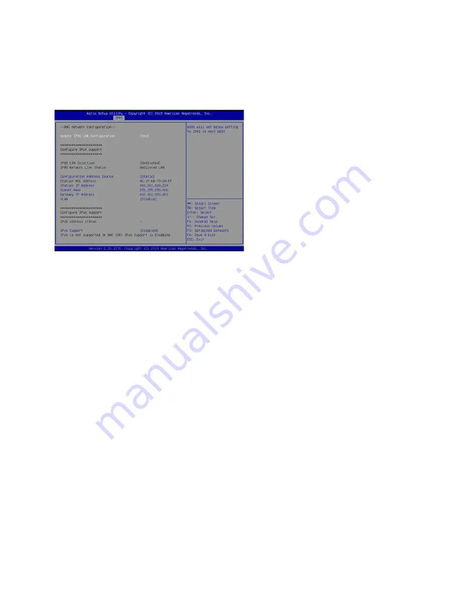
Figure 6: BIOS IPMI tab


4.

Set 

Update IPMI LAN configuration

 to 

Yes

.

5.

Set 

Configuration Address source

 to 

Static

.

6.

Configure the 

Station IP address

Subnet mask

, and 

Router address

.

These values must be valid and usable on your network!


Figure 7: BIOS IPMI: IP Address configured


7.

Press 

F4

 to save your changes and to exit the BIOS setup.

The system automatically shuts down and restarts.
The IPMI port is now accessible from the IP address you chose.
Now you can log on to the IPMI web interface and change the default password.

8.

To change the default password, open a web browser to http://<

IpAddressOfIPMIport

>, and

log on with the user name 

ADMIN

 and password 

ADMIN

 in caps.

IpAddressOfIPMIport

 is the station IP address you configured in step 6. The user name and

password boxes are always case-sensitive.

9.

Choose 

Configuration

 > 

Users

, and select the second user account (

ADMIN

 account).

10.

Click 

Modify User

, and change the password.

11.

(Optional) Set up alerts.
There is no audible alarm if there is an issue with a power supply unit. Other alerting

options are available. Each must be configured separately using details from your

environment.

To receive email alerts, change the settings at 

Configuration

 > 

SMTP

.

To receive SNMP traps, change the settings at 

Configuration

 > 

SNMP

.

To receive Syslog messages, change the settings at 

Configuration

 > 

Syslog

.

You configured the IPMI port and changed the default password. You may have also configured

your system to send alerts when certain situations arise.
  

How to configure the JBOD IPMI port

The JBOD chassis offers intelligent management with IPMI providing hardware health

monitoring and remote power control.

Содержание G4-40G-100-384T

Страница 1: ...ndant OS drive Yes OS drive hot swappable Yes OS drive size 1 TB RAID drive hot swappable Yes RAID version 60 Rail kit Yes Operating system Windows 2012 R2 Physical Height 8U Width 19 in Depth 26 5 in Weight with mounted rail kit or portable unit without a travel case 216 lbs Weight handling or portable unit in a travel case 227 lbs Media Monitoring interfaces 2 Speed 100 Gb Accepted transceivers ...

Страница 2: ...h appliance comes packed in a box or several boxes The boxes contain the various components necessary for a successful installation The G4 40G 100 384T appliance box contains the following components 1 Head unit with RAID drives preinstalled 1 Rail kit 2 Power supply cables 2 Ethernet cables 1 External SAS cable 1 Product Activation Information envelope containing the product license 1 Quick Start...

Страница 3: ...r remove the appliance from the cabinet to perform any maintenance 1 Mount the appliance in your cabinet Refer to the instructions on VIAVI Rail Kit page 10 Use a server lift if necessary Do not remove the drives from the chassis 2 Connect the cables Power Ethernet TAP Span IPMI optional 3 Insert the transceivers 4 Connect the KVM 5 Turn on the JBODs Caution JBODs must be turned on before the head...

Страница 4: ...4 2020 Viavi Solutions 3 Feb 2020 viavidoc com observerstart 6 Turn on the head unit A1 7 Set the ip address ...

Страница 5: ...device maintenance It allows you to monitor start stop and manage your appliance remotely regardless of whether the appliance is powered on 8 Install SFP transceivers page 6 1 into the open slots on the back of the capture card s 9 If you are connecting to SPAN mirror ports of a network switch connect a straight through Ethernet cable from the SPAN mirror ports on your switch to the SFP transceive...

Страница 6: ... the SFP modules Caution Wear a grounding strap when handling SFPs to avoid damaging them or other components Avoid exposure to laser radiation from optical components by keeping the dust plugs installed until you are ready to install the cables Your transceivers can be inserted into any open port and in any order You can hot swap the connected transceivers at any time but it is recommended you th...

Страница 7: ... the Apex UI 1 Navigate to https hostname where hostname is the IP address or DNS name for the appliance 2 Log into the interface using the username admin and default password admin Configuring the LOM or IPMI port Your appliance comes with an on board LOM or IPMI port that provides you a dedicated management channel for device maintenance It allows you to monitor start stop and manage your applia...

Страница 8: ... is the station IP address you configured in step 6 The user name and password boxes are always case sensitive 9 Choose Configuration Users and select the second user account ADMIN account 10 Click Modify User and change the password 11 Optional Set up alerts There is no audible alarm if there is an issue with a power supply unit Other alerting options are available Each must be configured separat...

Страница 9: ...dible alarm You should set up alerts to notify you of any power supply issues 1 Directly connect using your host computer to the JBOD IPMI port using an Ethernet cable 2 On the host computer open a web browser to http 192 168 1 99 and log on with the user name ADMIN and password ADMIN in caps If you have trouble connecting see JBOD IPMI reset FAQ 3 Make changes as needed such as Change the ADMIN p...

Страница 10: ...dentify the inner rack rails The chassis package includes one pair of rack rail assemblies in the rack mounting kit Each assembly consists of an inner rail that secures to the chassis and an outer rail that is attached directly to the rack The inner rails are etched with L Left side and R Right side The rail is on the correct side and mounted correctly if the lettering if face up Figure 8 Rail kit...

Страница 11: ...ack Figure 10 Extending and mounting outer rails 11 Hang the hooks of the rear section of the outer rail onto the square holes on the rear of the rack Take care that the proper holes are used so the rails are level If desired use screws and washers to secure the rear of the outer rail to the rear of the rack 12 Repeat for the other outer rail The rails are attached Next insert the server into the ...

Страница 12: ...t is dangerous for a single person to off load the heavy chassis from the rack without assistance Be sure to have sufficient assistance supporting the chassis when removing it from the rack Use a server lift 1 Pull the chassis forward out the front of the rack until it stops 2 Press the release latches on each of the inner rails downward simultaneously and move the chassis forward in the rack Figu...

Отзывы: