background image


2 - 2 9


2-2-6. 

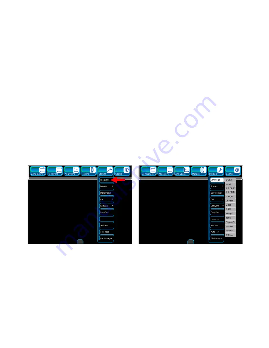
MULT I-LA NGUA GE SUP PORT  

T h e   D i g i t a l   R a d i o   T e s t   S y s t e m   c a n   b e   c o n f i g u r e d   t o   d i s p l a y   t h e   f u n c t i o n   t i l e s ,   t a b s   a n d   w i n d o w s   i n  
s e v e r a l   d i f f e r e n t   l a n g u a g e s .     T h e   l a n g u a g e s   a v a i l a b l e   a r e :  

ﺔﯾﺑرﻌﻟا 

简 体 中 文


繁 体 中 文


E n g l i s h  

F r a n ç a i s  

D e u t s c h  

日 本 語


한 국 의


M e l a y u  

P o l s k i  

P o r t u g u ê s  
русский 
E s p a ñ o l  

I t a l i a n o  


T o   c h a n g e   t h e   U n i t   t o   a   d i f f e r e n t   l a n g u a g e ,   s e l e c t   t h e   U t i l i t i e s   f u n c t i o n   t a b .     S e l e c t   t h e   L a n g u a g e  
d r o p   d o w n   i t e m   t o   d i s p l a y   t h e   L a n g u a g e   E x t e n d e d   I c o n s .   C h o o s e   t h e   d e s i r e d   l a n g u a g e   t a b .  


                                                                                              (   O p t i o n a l   L a n g u a g e s   a r e   s h o w n    
                                                                                                   f o r   d i s p l a y   p u r p o s e s   o n l y .   ) 
 

Содержание 8800 Series

Страница 1: ...DIGITAL RADIO TEST SYSTEM 8800 Series Operation Manual ...

Страница 2: ...VI Solutions Inc 2020 All rights reserved No part of this publication may be reproduced stored in a retrieval system or transmitted in any form or by any means electronic mechanical photocopying recording or otherwise without the prior permission of the publisher Original Printing Mar 2015 Revision G0 ...

Страница 3: ...ty information DFARS Restricted Rights Notices If software is for use in the performance of a U S Government prime contract or subcontract software is delivered and licensed as Commercial computer software as defined in DFAR 252 227 7014 Feb 2014 or as a commercial item as defined in FAR 2 101 a or as Restricted computer software as defined in FAR 52 227 19 Dec 2007 or any equivalent agency regula...

Страница 4: ...THIS PAGE INTENTIONALLY LEFT BLANK ...

Страница 5: ...supply or be supplied with AC or alternating voltage HOT SURFACE This surface may be hot to the touch EQUIPMENT GROUNDING PRECAUTION Improper grounding of equipment can result in electrical shock USE OF PROBES Check the specifications for the maximum voltage current and power ratings of any connector on the Unit before connecting it with a probe from a terminal device Be sure the terminal device p...

Страница 6: ...THIS PAGE INTENTIONALLY LEFT BLANK ...

Страница 7: ...aration of Conformity Certificate included with the Unit should remain with the Unit VIAVI recommends the operator reproduce a copy of the Declaration of Conformity Certificate to be stored with the Operation Manual for future reference ...

Страница 8: ...THIS PAGE INTENTIONALLY LEFT BLANK ...

Страница 9: ...y Hg Cadmium Cd Hexavalent Chromium Cr6 Polybrominated Biphenyls PBB Polybrominated Diphenyl Ethers PBDE 铅 汞 镉 六价铬 多溴联苯 多溴二苯醚 印刷板组件 Printed Board Assemblies X O O O O O 机箱子组件 Chassis subassembly X O O O O O 电源 Power Supply X O O O O O 电缆及电缆组件 Cables Cable Assemblies X O O O O O O Indicates that the toxic or hazardous substance contained in all of the homogenous materials for this component is belo...

Страница 10: ...n Use Period This indicates the period in years during which the hazardous substances described in Table 1 will not leak or mutate under normal operating conditions so that the use of the product will not result in any severe environmental problem any bodily injury or damage to assets The Environmental Protection Use period is valid only when the product is operated under the conditions defined in...

Страница 11: ...s CHAPTER 1 INTRODUCTION Provides an Introduction and a Brief Overview of Functions and Features Principles of Operation are also included CHAPTER 2 OPERATING INSTRUCTIONS Identifies and functionally describes all Controls Indicators and Connectors Provides UI interaction Provides a Turn On Procedure and Initial Adjustments Provides Operation Procedures Provides Applications CHAPTER 3 OPERATOR MAI...

Страница 12: ...tem Menu 2 26 2 2 5 Suspend Sleep Mode 2 27 2 2 6 Multi Language Support 2 29 2 3 Preventive Maintenance Checks and Services 2 31 2 3 1 General 2 31 2 3 2 Preventive Maintenance Procedures 2 31 2 3 2A Tools Materials and Equipment Required 2 31 2 3 2B Routine Checks 2 31 2 3 2C Schedule of Checks 2 31 2 4 Operation Under Usual Conditions 2 32 2 4 1 Turn On Procedure 2 32 2 4 2 Install Remove Licen...

Страница 13: ...4 3 3 3 Fuse Replacement 3 5 3 3 4 DMM Fuse Replacement 3 6 3 3 5 Feet Replacement 3 7 3 4 Preparation for Storage or Shipment 3 8 3 4A Packaging 3 8 3 4B Environment 3 8 APPENDICES A Connector Pin Out Tables A 1 A 1 I O Connectors A 1 A 2 MIC Connector Pin Out Table A 3 A 3 REMOTE Connector Pin Out Table A 4 A 4 ETHERNET Connector Pin Out Table A 5 A 5 USB Connector Pin Out Table A 6 B Abbreviati...

Страница 14: ...ES iv LIST OF TABLES TITLE PAGE I O Connectors Front Panel A 1 I O Connectors Rear Panel A 2 MIC Connector Pin Out Table A 3 REMOTE Connector Pin Out Table A 4 ETHERNET Connector Pin Out Table A 5 USB Connector Pin Out Table A 6 ...

Страница 15: ...cking material from the bottom packing mold Remove the protective plastic bag from the Digital Radio Test System and inspect the contents Place the protective plastic bag and packing material inside the shipping container Store the shipping container for future use should the Digital Radio Test System need to be returned shipped Checking Unpacked Equipment Check the equipment for damage incurred d...

Страница 16: ...vi Checking Unpacked Equipment cont ...

Страница 17: ... 112581 138803 139942 1 Battery Spare 67076 1 External DC Power Supply 67374 1 Front Cover 138167 1 Fuse Spare 5 A 32 Vdc Type F 56080 2 Manual Getting Started Paper 139254 1 Manual Operation CD 139274 1 Power Cable AC China 91803 1 Power Cable AC Continental Europe 27480 1 Power Cable AC North America 27478 1 Power Cable AC UK 27477 1 ...

Страница 18: ...RD ITEMS 8800 8800S 8800SX 112581 138803 139942 Battery Spare 67076 External DC Power Supply 67374 Front Cover 138167 Fuse Spare 5 A 32 Vdc Mini Blade 56080 Manual Getting Started Paper 139254 Manual Operation CD 139274 Power Cable AC China 91803 ...

Страница 19: ...ix Checking Unpacked Equipment cont STANDARD ITEMS Power Cable AC Continental Europe 27480 Power Cable AC North America 27478 Power Cable AC UK 27477 ...

Страница 20: ...ttenuator 20 dB 150 W 82560 Battery Charger External 114479 Battery Spare 67076 Case Soft Sided Carrying Case 114478 Case Transit 114477 DMM Test Leads 63936 Handset Microphone 112861 Manual Maintenance CD 113614 Power Cable DC Cigarette Lighter 62404 Power Sensor Bird 5017B 113309 Precision DTF VSWR Accessory Kit 114348 Rackmount Kit 114312 ...

Страница 21: ...sh Portuguese Malay Indonesian Korean Arabic Polish Russian Japanese German French Italian 8800 Series Opt01 8800 Series Opt02 8800 Series Opt03 8800 Series Opt04 8800 Series Opt05 8800 Series Opt09 8800 Series Opt10 8800 Series Opt11 8800 Series Opt12 8800 Series Opt13 8800 Series Opt14 8800 Series Opt15 8800 Series Opt20 8800 Series Opt300 8800 Series Opt301 8800 Series Opt302 8800 Series Opt303...

Страница 22: ... These optional items may be included if ordered Antenna Kit 114475 Attenuator 20 dB 150 W 38242 Battery Charger External 114479 Battery Spare 67076 Case Soft Sided Carrying Case 114478 Case Transit 114477 DMM Test Leads 63936 Handset Microphone 112861 ...

Страница 23: ...ent cont OPTIONAL ITEMS These optional items may be included if ordered Manual Maintenance CD 113614 Power Cable DC Cigarette Lighter 62404 Power Sensor Bird 5017B 113309 Precision DTF VSWR Accessory Kit 114348 Rackmount Kit 114312 ...

Страница 24: ...xiv THIS PAGE INTENTIONALLY LEFT BLANK ...

Страница 25: ...eries Digital Radio Test System is used for testing radios and related equipment B Nomenclature Cross Reference List COMMON NAME OFFICIAL NOMENCLATURE 8800 8800 Digital Radio Test System 8800S 8800S Digital Radio Test System 8800SX 8800SX Digital Radio Test System 8800 Series 8800 Series Digital Radio Test System Test Set Digital Radio Test Sytem or Unit 8800 Series Digital Radio Test System ...

Страница 26: ...nch operation or servicing A Capabilities Capabilities RF Receiver Testing Up to 1 GHz bandwidth AM FM frequency and level measurements RF Transmitter Testing Up to 1 GHz bandwidth AM FM 1 kHz 150 Hz and external modulation sources RF Power Meter Up to 50 W continuous 200 W with an external attenuator VSWR measurements Simple operation with few key strokes and textual displays Large Touch Screen D...

Страница 27: ...1 3 B Features Functions and Tiles LMR Optional Functions are shown for display purposes only ...

Страница 28: ...1 4 B Features cont Functions and Tiles Extended LMR Optional Functions are shown for display purposes only ...

Страница 29: ...1 5 B Features cont Functions and Tiles PTC Optional Functions are shown for display purposes only ...

Страница 30: ...1 6 B Features cont Functions and Tiles Extended PTC Optional Functions are shown for display purposes only ...

Страница 31: ...1 7 B Features cont Functions and Tiles Advanced Digital Optional Functions are shown for display purposes only ...

Страница 32: ...1 8 B Features cont Functions and Tiles Extended Advanced Digital Optional Functions are shown for display purposes only ...

Страница 33: ...ANT Port 20 dBm Input Power Alarm Typical T R Port 8800 49 dBm CW Input Power Alarm Typical 90 C Temperature Alarm Typical T R Port 8800S 8800SX 52 dBm CW Input Power Alarm Typical 90 C Temperature Alarm Typical FREQUENCY Range 2 to 1000 MHz Usable Range 100 kHz to 2 MHz Accuracy Same as Timebase Resolution 1 Hz OUTPUT LEVEL RANGE T R Connector 50 to 125 dBm ANT Connector 30 to 90 dBm GEN Connecto...

Страница 34: ...re degraded when the Unit is tuned to frequency of spurious signal RESIDUAL FM 20 Hz rms in 300 Hz to 3 kHz BW 4 Hz rms Typical 100 MHz 6 Hzrms Typical 800 MHz 11 Hzrms Typical 800 MHz RESIDUAL AM 5 rms in 300 Hz to 3 kHz BW MODULATION TYPES Analog None FM and AM Digital P25 DMR dPMR ARIBT98 and NXDN DTMF None FM and AM DCS None FM and AM Two Tone Sequence None FM and AM Tone Remote None FM and AM...

Страница 35: ...Hz FM Modulation Accuracy 20 300 Hz to 1 2 kHz 30 1 2 kHz FM Input Slope Positive voltage yields positive deviation AUD IN Input Range 3 V 30 V Switchable Loads 3 V Range 150 Ω 600 Ω 1 kΩ High Z 30 V Range High Z Input Levels 3 V Range 0 05 to 3 2 Vrms 30 V Range 3 to 30 Vrms FM Input Frequency Range 300 Hz to 5 kHz FM Input Level Sensitivity 3 V Range 1 kHz 35 mVrms Typical 30 V Range 1 kHz 350 m...

Страница 36: ...ominal 3 Vdc bias voltage Input Frequency Range 300 Hz to 3 kHz Modulation 0 to 80 Modulation Accuracy 20 300 Hz to 1 2 kHz 30 1 2 kHz AUD IN Input Range 3 V 30 V Switchable Loads 3 V Range 150 Ω 600 Ω 1 kΩ High Z 30 V Range High Z Input Levels 3 V Range 0 05 to 3 2 Vrms 30 V Range 3 to 30 Vrms FM Input Frequency Range 300 Hz to 5 kHz FM Input Level Sensitivity 3 V Range 1 35 mVrms Typical High Z ...

Страница 37: ...t RF GENERATOR cont Frequency Accuracy Timebase 2 Hz Output Level Audio Out Load Impedance 1 Ω Audio Level Out 0 to 1 57 Vrms Resolution 0 001 Vrms Accuracy 10 100 Vrms 30 Hz to 5 kHz Distortion 3 1 kHz rate sine 300 Hz to 3 kHz ...

Страница 38: ...lation AF Counter T R Connector 20 dBm Preamp OFF 40 dBm Preamp ON RF Error Meter DEMOD Meters Distortion SINAD Modulation AF Counter Maximum Input Level Receiver Measurements ANT Connector 10 dBm Auto Preamp OFF T R Connector 41 dBm AM 47 dBm CW FM DEMODULATION TYPES AM FM DMR dPMR ARIBT98 NXDN and P25 FM DEMOD IF BW 5 6 25 8 33 10 12 5 25 30 100 and 300 kHz Audio Filters BW C Wt BP CCITT BP NONE...

Страница 39: ... 5 dB Typical Normalize function completed Ext Attenuation 0 to 30 dB 0 01 dB resolution RF POWER METER CW Only Broadband RF Power into T R Connector Range 20 to 53 dBm Meter Floor 0 10 W 20 dBm Maximum T R Port Input Level 8800 50 W continuous 25 C 10 C Maximum T R Port Input Level 8800S 8800SX 125 W 25 C 10 C 50 W continuous Max ON of 30 sec and Min OFF of 90 sec for power levels 50 W Averaging ...

Страница 40: ...ccuracy 10 of reading 500 Hz to 100 kHz Deviation 5 of Reading 1 to 10 kHz Deviation 150 Hz and 1 kHz Rate 3 of reading 1 to 10 kHz Deviation 1 kHz to 1 5 kHz Rate Flatness 0 5 dB 20 Hz to 6 kHz Rate AM PERCENT MODULATION METER Meter Range 5 to 100 Meter Modes Peak Peak Peak Peak 2 RMS Resolution 0 001 Accuracy 5 of reading 1 kHz rate 30 to 90 modulation 3 kHz LPF ...

Страница 41: ...R Meter Optional Weighting User defined from C WT BP CCITT BP NONE 15 kHz LP 0 3 kHz LP 0 3 kHz HP 5 kHz LP 300 Hz to 5 kHz BP 300 Hz to 3 kHz BP 0 3 kHz to 20 kHz BP 3 kHz LP Display Range 0 to 100 dB Accuracy 1 dB reading 8 dB 50 dB DISTORTION METER Measurement Sources AUD IN DEMOD DEMOD FM 2 kHz Deviation IF BW set appropriately for received modulation BW AM 25 Modulation IF BW set appropriatel...

Страница 42: ... p to 90 Vp p Frequency Range 15 Hz to 20 kHz Resolution 0 1 Hz Accuracy 1 Hz AUDIO FREQUENCY LEVEL METER Measurement Sources AUD IN SCOPE Input Ranges AUD IN 3 V 30 V SCOPE 2 Vdc 40 Vdc Frequency Range 200 Hz to 5 kHz Load Selection AUD IN 3 V Input Range High Z 150 Ω 600 Ω 1 kΩ 30 V Input Range 10 kΩ SCOPE High Z Input Level AUD IN Connector 3 V Range 10 mVrms to 3 Vrms 30 V Range 1 to 30 Vrms S...

Страница 43: ...l Accuracy 10 of Full Scale DC to 5 kHz Horizontal Sweep 0 5 ms Div to 0 1 sec Div Horizontal Accuracy 3 of Full Scale Trigger Source Auto or Normal Internal Trigger Adjustment Variable on Vertical Scale Markers Two Markers Displays Vertical Measurement Voltage kHz Modulation Displays Delta in Time between Markers SPECTRUM ANALYZER Frequency Range 0 to 1000 MHz Frequency Span 10 kHz to 5 MHz 1 2 5...

Страница 44: ...MULTIMETER DMM AC DC Voltmeter Full Scale Ranges 200 mV 2 V 20 V 200 V 2000 V Auto 150 VAC RMS or VDC MAX input Category II Resolution 3 5 Digits 2000 Counts Accuracy AC 5 FS 1 Count 25mV DC 1 FS 1 Count AC DC Ammeter Full Scale Ranges 200 mA 2 A 20 A Auto 20 A Range uses Optional Shunt connected to Voltmeter Maximum Open Circuit Input Voltage 30 Vrms referenced to COMMON or EARTH GROUND Category ...

Страница 45: ...riable speed of 2 C minute Aging applies after 1 hr of operation External Reference 10 MHz IN 8800SX only Input Frequency Range 10 MHz 150 Hz Input Level 10 to 10 dBm Maximum Input Level 15 dBm FREQ FLEX EXTERNALLY REFERENCED TIMEBASE CALIBRATION Input Frequency Range 2 to 1000 MHz Reference Input Connector 20 dBm T R 40 dBm ANT Freq Flex Accuracy 0 5 Hz from External Source Applied Stability Agin...

Страница 46: ...cy Average Forward Power 4 of reading 166 mW Return Loss 0 to 23 dB VSWR 1 15 to 99 9 Burst Average Power Burst Average Power Range 13 5 to 500 W Average Burst Width 1 μs to 5 ms Repetitions Rate Min 200 Hz Duty Cycle D 0 001 to 1 0 D Burst Width Period Accuracy Burst Average Power 6 of reading 0 166 D mW Peak Envelope Power Peak Envelope Power Range 13 3 to 1300 W Peak Envelope Power Accuracy Bur...

Страница 47: ...tures below 20 C nor above 60 C Operation AC DC Power Supply 0 C to 40 C Battery Power 20 C to 50 C NOTE Battery operation over temperature is based on the actual temperature rise of the Battery and instrument usage Battery must not be subjected to temperatures below 20 C nor above 60 C RELATIVE HUMIDITY 5 to 95 MIL PRF 28800F Class 3 ALTITUDE DC Operation 4600 M MIL PRF 28800F Class 3 AC Operatio...

Страница 48: ...s B EN61000 3 2 Class D Safety UL 1950 CSA 22 2 No 234 and No 950 IEC 950 EN 60950 DC INPUT POWER Voltage Range 11 to 24 Vdc Maximum Power 55 W 65 W charging with Optional Battery Typical Power 30 W DC Fuse Mini Blade 5 A 32 Vdc Type F BATTERY Battery Type Lithium Ion Li Ion Battery Pack NOTE Battery must not be subjected to temperatures below 20 C nor above 60 C Operation Time Minimum Backlight S...

Страница 49: ...1 25 1 4 PRINCIPLES OF OPERATION The Digital Radio Test System contains the following assemblies ...

Страница 50: ...1 26 THIS PAGE INTENTIONALLY LEFT BLANK ...

Страница 51: ...CHAPTER 2 OPERATING INSTRUCTIONS 2 1 2 1 OPERATOR S CONTROLS INDICATORS AND CONNECTORS Front Panel ...

Страница 52: ...es 6 MIC Connector Used for connection to a Handset Microphone 7 DMM Fuse 3 A 250 V Type F 8 AMP Connector Digital Multimeter External Input for AC and DC current meter input 9 COM Connector Digital Multimeter External Input for DMM functions 10 V Ω Connector Digital Multimeter External Input for DMM AC or DC Voltmeter and Ohmmeter 11 HOME Key Provides access to a screen for the selection of User ...

Страница 53: ...are for connection to the Radio Transmitter for measuring in line power 18 IN LINE POWER IN Connector Used with optional hardware for connection to the load i e Antenna for measuring in line power 19 Arrow Keys Used for manual edit of numeric values 20 ANT Connector Used for over the air tests 21 Touch Screen Display Used for viewing menus and screens and for providing manual input for data and se...

Страница 54: ...n 2 USB Connector Allows connection of USB 2 0 devices e g USB memory stick 3 Ground Connector Used as a chassis ground point for an optional ground connection 4 DC IN Connector Used for External DC operation of the Unit or battery charging 5 REMOTE Connector Used for communicating with external equipment 6 10 MHz IN Connector Used to connect the Unit to an external frequency standard ...

Страница 55: ...2 5 2 2 FUNCTIONS AND TILES Functions and Tiles LMR Optional Functions are shown for display purposes only ...

Страница 56: ...2 6 2 2 FUNCTIONS AND TILES cont Functions and Tiles PTC Optional Functions are shown for display purposes only ...

Страница 57: ...2 7 2 2 FUNCTIONS AND TILES cont Functions and Tiles Advanced Digital Optional Functions are shown for display purposes only ...

Страница 58: ...2 8 2 2 FUNCTIONS AND TILES cont Functions and Tiles Tetra BS Optional Functions are shown for display purposes only ...

Страница 59: ... minimize mode default setting select the System icon tab to display the System icons NOTE If the gray icon is not visible the Hide Icons button on the System Menu has been selected Press the Open Close icon to display the System icons with status window Press the Open Close icon again to display the System icons in minimize mode ...

Страница 60: ...ated Switches between Internal or External 10 MHz reference Opens the Snapshot Tile Window Indicates touch screen functions are locked or unlocked Captures freezes the readings traces on the screen Indicates the Unit is controlled remotely Indicates Warnings and Error Messages Displays the level of charge remaining in the Battery Status window ...

Страница 61: ...on Windows ICON FUNCTION Switches between numeric entry pad and slider bar Sends Tile Windows to back of other Tile Windows on the screen Closes the Tile Window Alternates between the different views if applicable of the Tile Window Alternates between the different views if applicable of the Tile Window ...

Страница 62: ...arker to the lowest point on signal Moves the selected marker left to the next peak Supports press and hold functionality Moves the selected marker right to the next peak Supports press and hold functionality Moves the selected marker left to the next data point Supports press and hold functionality Moves the selected marker right to the next data point Supports press and hold functionality Moves ...

Страница 63: ...ive Touch Screen that is responsive to the touch of a human finger Gloves can be worn when utilizing the Touch Screen or a writing instrument e g stylus can be used on the Touch Screen The Digital Radio Test System UI is navigated locally using the Front Panel Touch Screen ...

Страница 64: ...mize minimize screen components to create custom display configurations The Launch Bar is located at the top of the UI The Launch Bar provides access to the Function Icons The Launch Bar is opened from minimize mode by clicking on the gray icon at the top of the screen NOTE If the gray icon is not visible the Hide Menu button on the System Menu has been selected The Launch Bar is minimized by clic...

Страница 65: ...on the Options installed in the Digital Radio Test System When the Launch Bar is set to minimize mode default setting select the gray icon at the top of the screen to display the Launch Bar NOTE If the gray icon is not visible the Hide Menu button on the System Menu has been selected Press a Function Icon to display the Dropdown Menu for the Function Press the gray bar at the bottom of the Launch ...

Страница 66: ...dows provide visual access to the Digital Radio Test System s operating parameters and measurement data Tile Windows are opened by selecting the Tile from the Function Dropdown Menu Tile Windows are closed by selecting the minimize icon at the bottom of the Tile Window ...

Страница 67: ...splay area and provides access to Tile parameters which may not be visible when the Tile Window is in other views Tile Windows can be moved anywhere on the display area except Full Screen view To move a Tile Window touch or click on the Tile Window s title block or background and drag the Tile Window to a new location on the display Tile Windows can be minimized to the Launch Bar where the Tile Wi...

Страница 68: ...e display area at any one time When an active Tile Window is closed and reopened the Digital Radio Test System positions the Tile Window in the last active state and position on the screen When multiple Tile windows are active on the screen the Tile windows can be switched back and forth using the switch icon ...

Страница 69: ...keypad The value is then enabled by pressing the unit of measurement or the Enter Button on the Numeric Keypad Press Cancel to void any un entered changes and close the Numeric Entry Window Pressing Cancel does not restore a changed value that has already been enabled entered Press Clear to reset a numeric value to zero To reset an un entered value to the previously defined value press Cancel Pres...

Страница 70: ...to adjust the precision setting Once the digit range is selected the value is increased or decreased using the Slider Bar or the Up and Down arrows The Up increase and Down decrease arrows are used to adjust the last value selected in the bounding box Values are active at the time the values are edited live edits Press Cancel to void any un entered changes and close the Slider Bar Pressing Cancel ...

Страница 71: ...e Arrow Keys allow the user to edit numeric values The selected values are changed by using the left right arrows or by using the up down arrows After a numeric value is changed press the ENTER button middle round button The Numeric Keypad automatically closes when using the Arrow Keys ...

Страница 72: ...g Parameters cont Keyboard The Keyboard is displayed when a Text Data Field is selected for editing The Keyboard functions similar to an external keyboard The Keyboard allows the user to enter alpha numeric content Data is enabled by pressing the Enter Key ...

Страница 73: ...d Function icons If an opened Dropdown Menu extends off of the UI the Dropdown Menu can be moved up or down on the UI to access Dropdown Menu Function icons If a Dropdown Menu contains expanded Function icons a gray arrow appears on the right side of the icon Select the Function icon to display the expanded Function icons ...

Страница 74: ...t E Dropdown Menus cont Field Selections Dropdown Menus are used to select pre defined Field selections If an opened Dropdown Menu extends off of the UI the Dropdown Menu can be moved up or down on the UI to access Dropdown Menu Field selections ...

Страница 75: ...indows are displayed with information or to request user interaction Locked Fields An editable field updates to the Locked state when the Digital Radio Test System experiences a condition which makes the field un editable A locked field cannot be edited until the lock out condition is resolved ...

Страница 76: ...aker to ON or OFF Audio Squelch Adjusts Audio Squelch level Squelch Value Selects Audio Squelch level display Menu Timeout Delay Adjust for timeout on Launch Bar for Menu to remain displayed Backlight Adjust for Backlight brightness System Reset Resets Digital Radio Test System to factory settings Suspend Select to place Digital Radio Test System in Suspend Sleep Mode Hide Menu Launch Bar is not d...

Страница 77: ... battery usage and increases the amount of time the Unit can operate on battery power Follow these instructions to place the Digital Radio Test System into suspend sleep mode 1 With the Unit running in active awake mode SYS Indicator is White press the HOME Key to display the System Menu SYS Indicator 3 HOME Key ...

Страница 78: ...lank and the internal RF hardware systems are shut OFF NOTE The Digital Hardware systems retain active status and no information or screen settings are lost in suspend sleep mode 3 When the Unit is in suspend sleep mode press the HOME Key once to display the current time and battery life remaining Press the HOME Key a second time to restore the system to active awake mode ...

Страница 79: ...ges available are ﺔ ﯾ ﺑ ر ﻌ ﻟ ا 简 体 中 文 繁 体 中 文 English Français Deutsch 日 本 語 한 국 의 Melayu Polski Português русский Español Italiano To change the Unit to a different language select the Utilities function tab Select the Language drop down item to display the Language Extended Icons Choose the desired language tab Optional Languages are shown for display purposes only ...

Страница 80: ...2 30 2 2 6 MULTI LANGUAGE SUPPORT cont EXAMPLE English Language Chinese Simplified Language English Language Chinese Simplified Language ...

Страница 81: ...d Equipment Required No tools or equipment are required for operator preventive maintenance Cleaning materials required are a lint free cloth and mild liquid detergent B Routine Checks Preventive Maintenance is limited to routine checks such as shown below Cleaning Dusting Wiping Checking for frayed cables Storing items not in use Covering unused receptacles Checking for loose nuts bolts or screws...

Страница 82: ... the Digital Radio Test System 1 Press the POWER Key to initialize the Unit and verify the SYS Indicator illuminates 2 The Opening Screen is displayed The operator can now choose the desired screen NOTE The Unit displays the last screen s accessed when the Unit was powered down POWER Key 3 SYS Indicator 3 ...

Страница 83: ...alled in the Unit associated with the License Install License Follow these instructions to install a License in the Unit 1 Select the Utiities Function Icon to display the Utilities Dropdown Menu Select the Software icon to display the Software extended icons Select the Options icon to display the Options Tile Window Options are shown for display purposes only ...

Страница 84: ... to the following directory on a USB Flash Drive Viavi License 4 Install the USB Flash Drive in the USB Connector and wait for the Unit to recognize the USB Flash Drive approximately 15 seconds 5 Select Copy from USB Button and verify the Status Field displays Copying from USB Drive When the copy process is completed the Status Field displays Copying from USB Done 6 Select Install License Button W...

Страница 85: ...s to remove the License from the Unit 1 Select the Utiities Function Icon to display the Utilities Dropdown Menu Select the Software icon to display the Software extended icons Select the Options icon to display the Options Tile Window Options are shown for display purposes only ...

Страница 86: ...E LICENSE cont Remove License cont 2 Select the Remove License button The following prompt is displayed 3 Enter the password and select the OK Button to remove the License Select the Cancel Button to cancel the License removal ...

Страница 87: ...lay the Software extended icons Select the Update icon to display the Update Tile Window 2 Using a PC access the following website Viavi com 8800 Download the zip file containing the System Software to the PC 3 After removing all files from a USB Flash Drive unzip the System Software files to the root directory of the USB Flash Drive 4 Confirm the Viavi folder is created in the root directory of t...

Страница 88: ...displays Files are ready to install select the Install Software Button Select the OK Button to continue Press the Cancel Button to abort the Software Load 8 When the Software load is completed the Unit prompts to cycle power NOTE Progress Bars are displayed showing the software installation progress 9 Cycle power and repeat Steps 6 to 8 until all displayed items have been installed in the Unit ...

Страница 89: ... Window 2 Select the File Name field use the Keyboard to select the file name and press Enter 3 Select the Store button NOTE Up to 100 setups can be saved Recall Function Window Follow these instructions to save a Function Window in the Unit 1 Select the Utilities Function Tab to display the Utilities Dropdown selections Select Store Recall to display the Store Recall Tile Window 2 Highlight the f...

Страница 90: ...e Snapshot Tile Window File Names are shown for display purposes only Save Snapshot Select the Save button to save the Snapshot with the file name shown in the File field File Names are shown for display purposes only Press the OK button to save the file name ...

Страница 91: ...New Folder Name field and use the Keyboard to select the folder name Press the OK button to save the folder name Create New File To create a new file name select the File Name field use the Keyboard to select the file name and press Enter File Names are shown for display purposes only Select the Save button and press the OK button to save the file name ...

Страница 92: ...n File Names are shown for display purposes only Select the file to be deleted file name shown in the File field Press the Delete button to display the Delete Confirmation Window Press the Delete button to delete the file or the Cancel button to escape from the Delete action ...

Страница 93: ...P Field 4 Enter the IP Address of the Target Unit into the Target IP Field 5 Select the Screen Settings Clear and Copy Button to clear all saved screens in the Target Unit and copy the saved screens from the Base Unit to the Target Unit 6 Select the Screen Settings Copy Button to copy the saved screens from the Base Unit to the Target Unit 7 Select the Scripts Clear and Copy Button to clear all Sc...

Страница 94: ... Ohm Meter and displays the measurement of resistance found in the circuit being tested DMM Configuration Window The DMM Configuration Window contains parameters for defining DMM measurements FIELD DESCRIPTION Reading Displays meter measurement The type of measurement being displayed Live Average Maximum or Minimum is selected from the Reading Type Drop down Menu Range Defines the vertical scale o...

Страница 95: ...R ARIB T98 and PDR C Advanced Digital Configuration The Advanced Digital configuration provides access to advanced digital test modes These modes include P25 Phase 2 HCPM and HDQPSK and DMR Repeater Sync For simplicity the Advanced Digital configuration also contains P25 Phase 1 and DMR test parameters which allows users to provide complete P25 Phase 1 and Phase 2 tests and DMR mobile and repeater...

Страница 96: ...ation Modes Press the Home Key to display the System Menu Select the Configuration field to display a selection menu of configuration modes LMR PTC Advanced Digital or TETRA Select the desired configuration mode to change the configuration mode of the Unit ...

Страница 97: ...se within the Digital Radio Test System The External reference refers to an external time base connected to the 10 MHz IN Connector 8800SX only The Freq Flex reference allows the user to calibrate the Digital Radio Test System to a clean external frequency reference and store that calibration reference within the Unit 8800 8800S The 8800 8800S offers the Internal reference and Freq Flex selections...

Страница 98: ... Modulation Function icon to display the Modulation Tile Window 4 Select the Receivers icon to display the Receivers Dropdown Menu Select the Analog Function icon to display the Analog Demod Tile Window 5 Select the Analyzers icon to display the Analyzers Dropdown Menu Select the Oscilloscope Function icon to display the Oscilloscope Tile Window 6 Select the Config icon to display the Config Dropd...

Страница 99: ...tion Tile Window 4 Select the View icon to expand the Modulation Tile Window 5 Select the Receivers icon to display the Receivers Dropdown Menu Select the Analog Function icon to display the Analog Demod Tile Window 6 Select the Analyzers icon to display the Analyzers Dropdown Menu Select the Oscilloscope Function icon to display the Oscilloscope Tile Window 7 The Oscilloscope Tile Window and the ...

Страница 100: ... display the Modulation Tile Window 4 Select the Receivers icon to display the Receivers Dropdown Menu Select the Digital Function icon to display the Digital Demod Tile Window 5 Select the Analyzers icon to display the Analyzers Dropdown Menu Select the Digital Plots Function icon to display the Digital Plots Tile Window 6 Select the Analyzers icon to display the Analyzers Dropdown Menu Select th...

Страница 101: ... the Modulation icon to display the Modulation Tile Window 3 Select the Receivers icon to display the Receivers Dropdown Menu Select the Receiver Function icon to display the Receiver Tile Window 4 Select the Receivers icon to display the Receivers Dropdown Menu Select the Digital Function icon to display the Digital Demod Tile Window 5 Select the Analyzers icon to display the Analyzers Dropdown M...

Страница 102: ...to display the Modulation Tile Window 3 Select the Receivers icon to display the Receivers Dropdown Menu Select the Receiver Function icon to display the Receiver Tile Window 4 Select the Receivers icon to display the Receivers Dropdown Menu Select the Digital Function icon to display the Digital Demod Tile Window 5 Select the Analyzers icon to display the Analyzers Dropdown Menu Select the Digita...

Страница 103: ... icon to display the Modulation Tile Window 3 Select the Receivers icon to display the Receivers Dropdown Menu Select the Receiver Function icon to display the Receiver Tile Window 4 Select the Receivers icon to display the Receivers Dropdown Menu Select the Digital Function icon to display the Digital Demod Tile Window 5 Select the Analyzers icon to display the Analyzers Dropdown Menu Select the ...

Страница 104: ...2 54 THIS PAGE INTENTIONALLY LEFT BLANK ...

Страница 105: ... needs recharging When the BAT Indicator is GREEN the battery is at 100 full charge When the BAT Indicator is AMBER the battery is charging If the battery level shown in the BAT Icon is 5 a Low Battery warning message is displayed The battery charger operates whenever the supplied External DC Power Supply or a suitable 11 to 24 Vdc DC Power source is applied to the Unit When charging the battery r...

Страница 106: ...uick performance evaluation Test results are shown next to the tests in the Pass Fail Counters 1 Select the Utilities icon to display the Utilities Dropdown Menu Select the Self Test Function icon to display the Self Test Tile Window 2 Select the Run button to initiate the Self Test ...

Страница 107: ...torage periods of more than six months The Battery must be removed when conditions surrounding the Unit are 20 C and 60 C DESCRIPTION This procedure is used to recharge the Battery in the Unit with an External DC Power Supply 1 Connect the External DC Power Supply to the DC IN Connector on the Unit 2 Connect the AC Power Cable to the AC PWR Connector on the External DC Power Supply and an appropri...

Страница 108: ...BATTERY PACK IN NORMAL WASTE DO NOT SHORT CIRCUIT OR FORCE DISCHARGE OF THE LITHIUM ION BATTERY PACK AS THIS MIGHT CAUSE THE LITHIUM ION BATTERY PACK TO VENT OVERHEAT OR EXPLODE REMOVE 1 Verify the Unit is OFF and is not connected to AC power 2 Unlatch the Battery Cover to expose the Battery 3 Disconnect the Battery Wire Harness connecting the Battery to the Unit and remove the Battery INSTALL 1 I...

Страница 109: ...IRE REPLACE ONLY WITH FUSES OF THE SPECIFIED VOLTAGE AND CURRENT RATINGS 5 A 32 VDC MINI BLADE FUSE REMOVE 1 Verify the Unit is OFF and is not connected to AC power 2 Unlatch the Battery Cover to expose the Fuse 3 Locate and remove the Fuse INSTALL 1 Install the Fuse 2 Relatch the Battery Cover on the Unit Battery Wire Harness Battery Cover Fuse ...

Страница 110: ... CAUTION FOR CONTINUOUS PROTECTION AGAINST FIRE REPLACE ONLY WITH FUSES OF THE SPECIFIED VOLTAGE AND CURRENT RATINGS 3 A 250 V TYPE F FUSE REMOVE Remove the DMM fuse cover and DMM fuse from the Unit and replace the DMM fuse INSTALL Install the DMM fuse and fuse cover in the Unit DMM Fuse Cover DMM Fuse ...

Страница 111: ...move screw from the Unit Remove front foot and flip foot from the Unit Lift Tab on Rear Foot and remove Rear Foot from the Unit INSTALL Install the flip foot and front foot on the Unit Install the screw in the Unit and tighten to 6 in lbs Install Rear Foot in the Unit Flip Foot Front Foot Screw Rear Foot ...

Страница 112: ...in the container Seal the shipping container with approved sealing tape Mark FRAGILE on the top bottom and all sides of the shipping container B Environment The Unit should be stored in a clean dry environment In high humidity environments protect the Unit from temperature variations that could cause internal condensation The following environmental conditions apply to both shipping and storage Te...

Страница 113: ...na Plug Female INPUT GEN N Female OUTPUT HEAD PHONES 2 5 mm CIRCULAR OUTPUT IN LINE POWER IN N Female INPUT IN LINE POWER OUT N Female OUTPUT MIC 6 Pin CIRCULAR Female INPUT OUTPUT Refer to Table A 3 for MIC Connector description SCOPE BNC Female INPUT T R N Female INPUT OUTPUT USB USB 2 0 INPUT OUTPUT Refer to Table A 6 for USB Connector description V Ω DMM Banana Plug Female INPUT Table A 1 I O ...

Страница 114: ...J45 INPUT OUTPUT Refer to Table A 5 for ETHERNET Connector description GROUND 2 5 mm CIRCULAR INPUT OUTPUT REMOTE 44 Pin D SUB Female INPUT OUTPUT Refer to Table A 4 for REMOTE Connector description USB USB 2 0 INPUT OUTPUT Refer to Table A 6 for USB Connector description 10 MHz IN BNC Female INPUT Table A 2 I O Connectors Rear Panel ...

Страница 115: ...A 3 A 2 MIC CONNECTOR PIN OUT TABLE A F E D C B PIN NO SIGNAL NAME A GND B SPEAKER C PTT D MIC E MICSEL1 F MICSEL2 Table A 3 MIC Connector Pin Out Table ...

Страница 116: ...GND 29 REM_GPIO 1 8 PPC_ERX_N 30 REM_GPIO 3 9 PPC_ETX_N 31 USB3_VBUS 10 GND 32 USB3_GND 11 PPCUSR_RTS 33 5V_ACC 12 PPCUSR_RXD 34 PPCDBUG_RXD 13 REM_GPIO 7 35 GND 14 REM_GPIO 6 36 OMAPRCI_RXD 15 REM_GPIO 2 37 GND 16 USB3_FD_N 38 PPC_ERX_P 17 USB3_FD_P 39 GND 18 OMAPCON_TXD 40 REM_GPIO 4 19 OMAPCON_RXD 41 REM_GPIO 0 20 GND 42 OMAPCON_RTS 21 OMAPRCI_TXD 43 OMAPCON_CTS 22 OMAPRCI_CTS 44 BKBOX Table A ...

Страница 117: ...A 5 A 4 ETHERNET CONNECTOR PIN OUT TABLE 1 8 PIN NO SIGNAL NAME 1 TX 2 TX 3 RX 4 NOT USED 5 NOT USED 6 RX 7 NOT USED 8 NOT USED Table A 5 ETHERNET Connector Pin Out Table ...

Страница 118: ...A 6 A 5 USB CONNECTOR PIN OUT TABLE 1 4 PIN NO SIGNAL NAME 1 VCC 2 D 3 D 4 GND Table A 6 USB Connector Pin Out Table ...

Страница 119: ...e g For Example EMC Electromagnetic Compatibility EMI Electromagnetic Interference Err Error ESC Escape Est Estimated F F Female FH Frequency Hop Fgen Function Generator FM Frequency Modulation FPGA Field Programmable Gate Array FREQ Frequency G Gen Generate Generator GHz Gigahertz 109 Hertz H H Hour HI High HP High Pass Hr Hour HW Hardware Hz Hertz I ID Identification i e That is IF Intermediate ...

Страница 120: ...erature Temp Temperature TNC Threaded Neill Concelman T R Transmit Receive TX Transmit U UHF Ultra High Frequency UI User Interface USB Universal Serial Bus UUT Unit Under Test V V Volt VAC Volts Alternating Current Vdc Volts Direct Current VHF Very High Frequency Vol Volume Vp Volta Peak Vrms Volts Root Mean Square VSWR Voltage Standing Wave Ratio W W Watt Y Y Year ...

Страница 121: ...AVI Solutions North America 1 844 GO VIAVI 1 844 468 4284 Latin America 52 55 5543 6644 EMEA 49 7121 862273 APAC 1 512 201 6534 All Other Regions viavisolutions com contacts 139274 Rev G0 139274 June 2020 ...

Отзывы: