


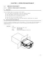


3 - 1 0
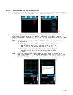
3-3-2.
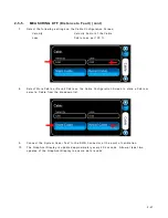
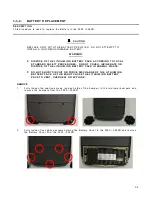
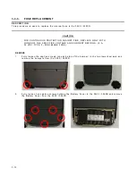
BA T T ERY RE PLA CE MENT (cont)
R E M O V E ( c o n t )
3 .
D i s c o n n e c t t h e B a t t e r y W i r e H a r n e s s a n d r e m o v e t h e B a t t e r y f r o m t h e 3 5 5 0 / 3 5 5 0 R .
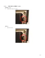
I N S T A L L
1 .
I n s t a l l t h e B a t t e r y i n t h e 3 5 5 0 / 3 5 5 0 R a n d c o n n e c t t h e B a t t e r y W i r e H a r n e s s .
2 .
I n s t a l l t h e B a t t e r y C o v e r o n t h e 3 5 5 0 / 3 5 5 0 R a n d t i g h t e n f i v e c a p t i v e s c r e w s ( 8 i n / l b s . ) .
Содержание 3550
Страница 1: ...3550 3550R Communications Test Set Operation Manual ...
Страница 3: ......
Страница 5: ...THIS PAGE INTENTIONALLY LEFT BLANK ...
Страница 7: ...THIS PAGE INTENTIONALLY LEFT BLANK ...
Страница 9: ...THIS PAGE INTENTIONALLY LEFT BLANK ...
Страница 26: ...1 3 B Features Functions and Tiles LMR Optional Functions are shown for display purposes only ...
Страница 27: ...1 4 B Features cont Functions and Tiles Extended LMR Optional Functions are shown for display purposes only ...
Страница 28: ...1 5 B Features cont Functions and Tiles PTC Optional Functions are shown for display purposes only ...
Страница 29: ...1 6 B Features cont Functions and Tiles Extended PTC Optional Functions are shown for display purposes only ...
Страница 104: ...3 13 3 3 3 FUSE REPLACEMENT cont REMOVE cont 3 Locate and remove the Fuse INSTALL 1 Install the Fuse ...
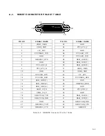
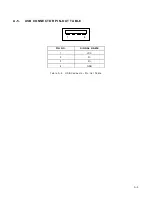
Страница 114: ...A 5 A 5 USB CONNECTOR PIN OUT TABLE 1 4 PIN NO SIGNAL NAME 1 VCC 2 D 3 D 4 GND Table A 5 USB Connector Pin Out Table ...
Страница 115: ...A 6 THIS PAGE INTENTIONALLY LEFT BLANK ...