


19
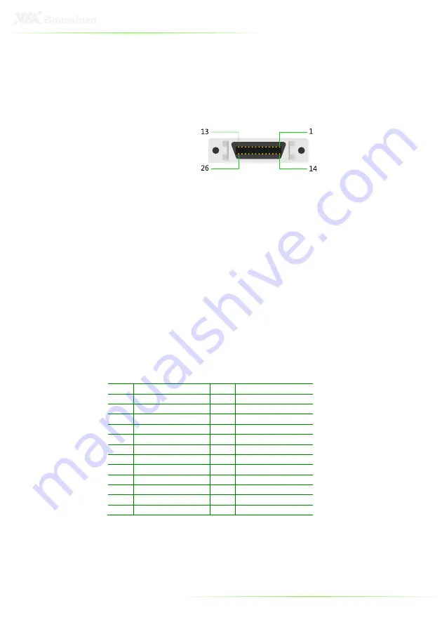
LVDS Connector: LVDS2
The VIPRO VP7806 supports one external 24-bit single channel
LVDS interface connector using D-Sub 26-pin connector on top
I/O side. The connector also carries the inverter control signals.
Built in LCD Backlight On/Off and Brightness
control signals
LVDS2 connector includes the following control signals: BLON,
and BRIGHTNESS_CTL. In ad12V, +5V and Ground Pin
signals are also included, allowing developers and applications to
connect these signals to the LCD Inverter to implement the LCD
backlight On/Off control and brightness control.
•
Provides the “BLON” signal that the inverter module requires for
controlling the Backlight On/Off feature.
•
Provides 12V and 5V as the Inverter Power Source.
•
Provides the “BRIGHTNESS_CTL
” signal pin that can be connected
to LCD’s Inverter that allow
applicant to implement brightness
adjustment through customer’s software utility.
LVDS2
LVDS2
LVDS2
LVDS2
Pin Signal
Pin Signal
1
+LCLK2
14
GND
2
-LCLK2
15
+LD2C3
3
GND
16
-LD2C3
4
+LD2C2
17
GND
5
-LD2C2
18
GND
6
GND
19
+LD2C1
7
+LD2C0
20
-LD2C1
8
-LD2C0
21
GND
9
SPCLK2
22
SPD2
10
PVDD2
23
PVDD2
11
IVDD2_12V
24
IVDD2_12V
12
BLON2
25
BRIGHTNESS_CTL2
13
IVDD2_5V
26
IVDD2_5V
Onboard LCD signal power 3.3V/5V switch
The system also provides jumper header (PVDD2_SEL) onboard
for selecting the LCD signal power of 3.3V or 5V for LVDS2. The
default setting of PVDD2 is 3.3V.
Содержание VIPRO VP7806
Страница 10: ...X...
Страница 11: ...1 1 Product Overview...
Страница 18: ...8 VIPRO VP7806 DIMENSIONS Front View Back View...
Страница 19: ...9 Right and Left View...
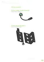
Страница 20: ...10 ACCESSORIES Power cable 2 pole Phoenix Part 99G33 250073 Panel mount Brackets Part 99G42 091536 A1...
Страница 22: ...12...
Страница 24: ...14 INTRODUCTION OF I O LAYOUT Front View Layout Top View Layout...
Страница 25: ...15 Bottom View Layout Right and Left View Layout...
Страница 43: ...33 Step 4 Step 4 Step 4 Step 4 Secure the VIPRO VP7806 to the wall with four screws...
Страница 45: ...35 Step Step Step Step 2 2 2 2 Secure the both mounting brackets to the wall with four wall mounting screws...
Страница 51: ...41 4 BIOS Setup This chapter gives a detailed explanation of the BIOS setup functions...
Страница 66: ...56 INTEGRATED PERIPHERALS...
Страница 74: ...64 FREEDOS CONFIGURATION Boot into FreeDOS The system will boot to FreeDOS Settings Disabled Enabled...