background image


VIA Mobile360 M820 User Manual

28

Step 5

Install the camera bracket on the appropriate location of your vehicle. 

Figure 45: Installing the camera bracket with FOV-190 camera on your vehicle

Caution:

Once the camera bracket has been installed, it cannot be removed. Forcibly removing it could damage the double-
sided adhesive tape.

Step 6

Slightly loosen the four screws (M3x6) of the internal bracket to allow movement. Then adjust the internal 

bracket to the preferred angle of your FOV-190 camera. Once the camera angle has been positioned, tighten 

the four screws to firmly secure the camera.

Figure 46: Adjusting the FOV-190 camera angle

Содержание Mobile360 M820

Страница 1: ...USER MANUAL VIA Mobile360 M820 Fanless ultra compact in vehicle safety system with flexible ADAS SVS and DMS integration options 1 01 28042021 ...

Страница 2: ...h change VIA Technologies Inc reserves the right the make changes to the products described in this manual at any time without prior notice Regulatory Compliance FCC A Radio Frequency Interference Statement This equipment has been tested and found to comply with the limits for a class A digital device pursuant to part 15 of the FCC rules These limits are designed to provide reasonable protection a...

Страница 3: ...r cord where people will step on it Always unplug the power cord before inserting any add on card or module If any of the following situations arise get the equipment checked by authorized service personnel The power cord or plug is damaged Liquid has entered into the equipment The equipment has been exposed to moisture The equipment is faulty or you cannot get it work according to User s Manual T...

Страница 4: ...S DMS camera with IR and mounting bracket 99G40 08115Z 1 0MP FOV 35 720p CMOS automotive grade camera for BSD 99G40 08116Z 1 0MP FOV 190 720p CMOS automotive grade camera for SVS Rear ADAS 99G33 230406 15M FAKRA cable M360 CBKT 00A1 Camera mounting braket for SVS BSD 42mm x 28 2mm x 32 3mm 1 65 x 1 11 x 1 27 Display Accessories Part Number Description 99G73 01034C 10 Resistive touch monitor 1280x8...

Страница 5: ...VIA Mobile360 M820 User Manual v Mounting Options Part Number Description M360 SBKT 00A1 Mounting bracket 337 2mm x 185mm x 62mm ...

Страница 6: ...ro USB 2 0 Port 7 2 4 Gigabit Ethernet Port 8 2 5 Micro SD Card Slot 8 2 6 SIM Card Slot 9 2 7 DIO Port 10 2 8 Headphone and Mic in Port 10 2 9 COM Port 10 2 10 CAN Bus Port 11 2 11 FAKRA Connectors 11 2 12 Power Button 11 2 13 DC in Jack 12 2 14 DC out Jack 12 2 15 Antenna Connectors 13 3 Onboard I O 14 3 1 MiniPCIe Slot 14 4 Hardware Installation 15 4 1 Installing the 2 5 SATA HDD SSD 15 4 2 Ins...

Страница 7: ... B Installing Automotive Grade Cameras to the Camera Brackets 26 B 1 Installing the FOV 190 Automotive Grade Camera to the Camera Bracket 26 B 2 Installing the FOV 35 Automotive Grade Camera to the Camera Bracket 29 B 3 Installing the Front ADAS Automotive Grade Camera 33 B 4 Installing the DMS Automotive Grade Camera 37 Appendix C Installing Mounting Bracket 40 ...

Страница 8: ...SD bay 15 Figure 24 Removing the SATA HDD SSD bays 15 Figure 25 Installing the 2 5 SATA HDD SSD 16 Figure 26 Reinstalling the SATA HDD SSD bays 16 Figure 27 Installing the Wi Fi antennas 17 Figure 28 Installing the GPS antenna 17 Figure 29 Connecting the FOV camera to the FAKRA cable 18 Figure 30 Connecting the FAKRA cable to the FAKRA connector 18 Figure 31 Unplugging the FAKRA cable 19 Figure 32...

Страница 9: ...ns cover 34 Figure 55 Installing the Front ADAS camera 34 Figure 56 Adjusting the Front ADAS camera angle 35 Figure 57 Connecting the power and microphone speaker adapter cable 35 Figure 58 Connecting the 2 pole power connector for the Front ADAS camera 36 Figure 59 Connecting the HP MIC GND wires for the Front ADAS camera 36 Figure 60 Removing the double sided adhesive tape protective cover 37 Fi...
Страница 10: ... LED color definition 8 Table 06 SIM card slot pinouts 9 Table 07 SIM card slot pinouts 9 Table 08 DIO port pinouts 10 Table 09 Headphone and Mic in port pinouts 10 Table 10 COM port pinouts 10 Table 11 CAN bus ports pinouts 11 Table 12 FAKRA connector pinout 11 Table 13 Power button behavior description 12 Table 14 Power button behavior description 12 Table 15 DC out jack pinouts 12 Table 16 Mini...

Страница 11: ...6GB eMMC flash memory a SIM card slot DIO COM and a headphone mic in port The VIA Mobile360 M820 supports high computing power operation with low power consumption and it has a built in power management system that protects from power surges guarding against damage from transient car power With the power management system it is capable of handling a wide range of DC power inputs from 9 36V 1 1 Key...

Страница 12: ...1 1 9 Embedded Operating System Ready The VIA Mobile360 M820 features a complete software evaluation image based on Yocto 2 3 1 2 Product Specifications Processor Qualcomm APQ8096A Embedded Processor Two high performance Kryo cores up to 2 054GHz Two low power Kryo cores up to 1 593GHz System Memory 4GB LPDDR4 SDRAM Storage 16GB eMMC flash memory 2 x M 2 SATA slots 2 x 2 5 SATA HDD SSD storage bay...

Страница 13: ...r button Back Panel I O 1 x HDMI port 1 x DIO port 1 x COM port 1 x CAN bus port 1 x Gigabit Ethernet port 9 x FAKRA connectors for camera in 1 x Headphone and Mic in port 4 x Antenna connectors for Wi Fi 4G GPS 1 x 4 pole Phoenix 9 36 V DC in 1 x 2 pole Phoenix 12V DC out Power Supply 9 36V DC in with IGN Operating System Yocto 2 3 Operating Temperature 20 C 70 C Storage Temperature 20 C 70 C Ope...

Страница 14: ...nding on the actual situation and environment It is highly recommended to execute a solid testing program and take all variables into consideration when building the system Please ensure that the system is stable under at the required operating temperature in terms of application 2 Please note that the lifespan of the onboard eMMC UFS memory chip may vary depending on the amount of access More fre...

Страница 15: ...VIA Mobile360 M820 User Manual 5 Figure 02 Back panel I O layout Figure 03 Dimensions of the VIA Mobile360 M820 front view Figure 04 Dimensions of the VIA Mobile360 M820 side view ...

Страница 16: ...VIA Mobile360 M820 User Manual 6 Figure 05 Dimensions of the VIA Mobile360 M820 bottom view ...

Страница 17: ...Signal 1 D2 11 GND 2 GND 12 CLK 3 D2 13 CEC 4 D1 14 NC 5 GND 15 DDC_CLK 6 D1 16 DDC_DATA 7 D0 17 GND 8 GND 18 HDMI_5V 9 D0 19 PLUG_DET 10 CLK Figure 06 HDMI port diagram Table 01 HDMI port pinouts 2 2 USB 3 0 Ports The VIA Mobile360 M820 is equipped with two USB 3 0 ports on the front panel Each USB 3 0 port has a maximum data transfer rate of up to 5Gbps and is backwards compatible with the USB 2...

Страница 18: ...nown as RJ 45 It is fully compliant with the IEEE 802 3 10BASE T 802 3u 100BASE TX and 802 3ab 1000BASE T standards The pinouts of the Gigabit Ethernet port are shown below Pin Signal 1 TX1 2 TX1 3 TX2 4 TX2 5 TX3 6 TX3 7 TX4 8 TX4 Figure 09 Gigabit Ethernet port diagram Table 04 Gigabit Ethernet port pinouts The Gigabit Ethernet port RJ 45 is equipped with two LED indicators on the front side to ...

Страница 19: ...d Slot The VIA Mobile360 M820 comes with an optional SIM card slot located on the front panel that supports 4G SIM cards SIM card usage on the VIA Mobile360 M820 requires that a 4G module is installed in the miniPCIe slot enabling the 4G functionality otherwise the SIM card slot will be disabled The SIM card slot is designed for use with 4G modules that do not support built in SIM card slots The p...

Страница 20: ...a Headphone and Mic in port located on the back panel The Headphone and Mic in port is for connecting external speakers such as a headphone or a microphone The pinouts of the Headphone and Mic in port are shown below Pin Signal 1 MIC1 2 Jack_det 3 HPH_GND_SENSE_CONN 4 CDC_HPH_R_CONN 5 CDC_HPH_L_CONN Figure 13 Headphone and Mic in port diagram Table 09 Headphone and Mic in port pinouts 2 9 COM Port...

Страница 21: ...T 1A Figure 15 CAN bus port diagram Table 11 CAN bus ports pinouts 2 11 FAKRA Connectors The VIA Mobile360 M820 is equipped with nine FAKRA connectors located on the back panel The FAKRA connectors are for FOV 35 and FOV 190 automotive grade cameras The pinouts of the FAKRA connectors are shown below Pin Signal 1 RIN_P 2 GND Figure 16 FAKRA connector diagram Table 12 FAKRA connector pinout 2 12 Po...

Страница 22: ...360 M820 integrates a 4 pole Phoenix DC in jack that carries 9 36V DC external power input The pinouts of the 4 pole Phoenix DC in jack are shown below Pin Signal 1 DC IN 2 DC IN 3 GND 4 GND Figure 18 DC in jack diagram Table 14 Power button behavior description 2 14 DC out Jack The VIA Mobile360 M820 integrates a 2 pole Phoenix DC out jack that provides 12V DC power output The pinouts of the 2 po...

Страница 23: ...onnectors located on the back panel Two antenna connectors are used for Wi Fi antennas while the other two antenna connectors are used for GPS and 4G antennas The Wi Fi GPS and 4G antenna connectors diagrams are shown below Figure 20 Wi Fi antenna connectors diagram Figure 21 GPS and 4G antenna connectors diagram ...

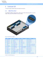
Страница 24: ...E 27 GND 28 VDD1V5 3 Reserved 4 GND 29 GND 30 Reserved 5 Reserved 6 VDD1V5 31 Reserved 32 Reserved 7 Reserved 8 USIM_VCC 33 Reserved 34 GND 9 GND 10 USIM_DATA 35 GND 36 MINI_PCIE_USB_DM 11 Reserved 12 USIM_CLK 37 GND 38 MINI_PCIE_USB_DM 13 Reserved 14 USIM_RST 39 VDD3V3_MPCIE 40 GND 15 GND 16 USIM_VPP 41 VDD3V3_MPCIE 42 Reserved 17 Reserved 18 GND 43 GND 44 Reserved 19 Reserved 20 MPCIE_W_DISABLE ...

Страница 25: ...er components Electrostatic discharge ESD can damage some components 4 1 Installing the 2 5 SATA HDD SSD Step 1 Insert the key and turn it in a counter clockwise direction to unlock the SATA HDD SSD bay Then unscrew the two thumbscrews Figure 23 Unlocking the SATA HDD SSD bay Step 2 Gently pull out the SATA HDD SSD bays to disengage it from the chassis completely Figure 24 Removing the SATA HDD SS...

Страница 26: ...nual 16 Step 3 Slide in the 2 5 SATA HDD SSD into the SATA HDD SSD bay Then secure it with four screws Figure 25 Installing the 2 5 SATA HDD SSD Step 4 Reinstall the SATA HDD SSD bays Figure 26 Reinstalling the SATA HDD SSD bays ...

Страница 27: ...the back panel of the VIA Mobile360 M820 Step 2 Install the provided two Wi Fi antennas Figure 27 Installing the Wi Fi antennas 4 3 Installing the GPS Antenna Step 1 Locate the GPS antenna connector on the back panel of the VIA Mobile360 M820 Step 2 Install the provided GPS antenna Figure 28 Installing the GPS antenna ...

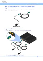
Страница 28: ... with the FAKRA cable s connector Then insert the camera connector until the locking clips lock the connector in place Figure 29 Connecting the FOV camera to the FAKRA cable Step 2 Connect the FAKRA cable to the FAKRA connector for camera in on the Mobile360 M820 Figure 30 Connecting the FAKRA cable to the FAKRA connector ...

Страница 29: ...0 User Manual 19 4 5 Unplugging the FAKRA Cable Step 1 Firmly press and hold the locking clip on the FAKRA cable s connector Step 2 Then pull the FAKRA cable s connector to unplug it Figure 31 Unplugging the FAKRA cable ...

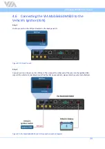
Страница 30: ... located on the back panel I O Figure 32 DIO port s pin 8 Step 2 Connect a wire on the pin no 8 on DIO port Then connect the other end of the wire into the Ignition IGN signal of the vehicle For details where to find the IGN on your vehicle please refer to your car manufacturer Figure 33 VIA Mobile360 M820 and IGN connection method diagram ...

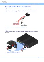
Страница 31: ...To install the wire first loosen the respective screws on the Phoenix plug to DC jack before inserting each wire Figure 34 Connecting the battery cables onto the Phoenix plug to DC jack Step 2 Connect the Phoenix plug to DC jack into the DC in jack on the VIA Mobile360 M820 and then secure it with its two screws Figure 35 Connecting the Phoenix plug to DC jack ...

Страница 32: ...tance For technical support and additional assistance always contact your local sales representative or board distributor or go to https www viatech com en support technical support for technical support For OEM clients and system integrators developing a product for long term production other code and resources may also be made available Please visit our website at https www viatech com en about ...

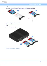
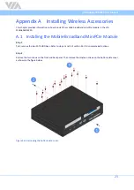
Страница 33: ... the VIA Mobile360 M820 A 1 Installing the Mobile Broadband MiniPCIe Module Step 1 First remove the two SATA HDD bays Refer to steps 1 and 2 of section 44 1 for complete instructions Step 2 Remove the two screws on the front and back panel Then remove the nineteen screws on the bottom plate cover as shown in the figure below Figure 36 Unscrewing the bottom plate cover ...

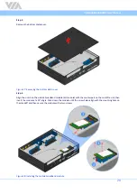
Страница 34: ...4 Align the notch on the mobile broadband module 4G module with the counterpart on the miniPCIe slot then insert the module at a 30 angle Push down the module until the screw holes align with the mounting hole on the standoff and then secure the module with a two screws Figure 38 Installing the mobile broadband module ...

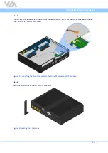
Страница 35: ... micro RF connector labeled MAIN on the mobile broadband module Then reinstall the bottom plate cover Figure 39 Connecting the 4G antenna cable to the micro RF connector on the module Step 6 Install the 4G antenna on the 4G antenna connector Figure 40 Installing the 4G antenna ...

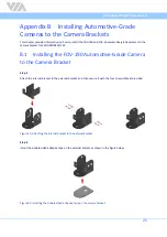
Страница 36: ...DMS BSD FCW B 1 Installing the FOV 190 Automotive Grade Camera to the Camera Bracket Step 1 Attach the internal bracket to the external bracket and then secure it with the four screws M3x6 provided Figure 41 Attaching the internal bracket to the external bracket Step 2 Install the double sided adhesive tape on the external bracket as shown in the figure below Figure 42 Installing the double sided ...

Страница 37: ...cing upward Install the FOV 190 camera on the internal bracket and then secure it with the two screws M3x8 provided Figure 43 Installing the FOV 190 camera on the camera bracket Step 4 Remove the protective cover of the double sided adhesive tape Figure 44 Removing the double sided adhesive tape protective cover ...

Страница 38: ...racket has been installed it cannot be removed Forcibly removing it could damage the double sided adhesive tape Step 6 Slightly loosen the four screws M3x6 of the internal bracket to allow movement Then adjust the internal bracket to the preferred angle of your FOV 190 camera Once the camera angle has been positioned tighten the four screws to firmly secure the camera Figure 46 Adjusting the FOV 1...
Страница 39: ...ernal bracket to the external bracket and then secure it with the four screws M3x6 provided Figure 47 Attaching the internal bracket to the external bracket Step 2 Install the double sided adhesive tape on the external bracket as shown in the figure below Figure 48 Installing the double sided adhesive tape on the camera bracket ...

Страница 40: ...with the text label facing downward before installing it on the internal bracket Figure 49 Preparing the FOV 35 camera Step 4 Install the FOV 35 camera on the internal bracket and then secure it with the two screws M3x8 provided Figure 50 Installing the FOV 35 camera on the camera bracket ...

Страница 41: ...VIA Mobile360 M820 User Manual 31 Step 5 Remove the protective cover of the double sided adhesive tape Figure 51 Removing the double sided adhesive tape protective cover ...

Страница 42: ...racket on the appropriate location of your vehicle Figure 52 Installing the camera bracket with FOV 35 camera on your vehicle Caution Once the camera bracket has been installed it cannot be removed Forcibly removing it could damage the double sided adhesive tape ...

Страница 43: ... intended to be placed in the center of the vehicles windshield below the rear view mirror The housing also includes a speaker to playback the audio alerts from the VIA Mobile360 M820 system as well as a microphone which can be used to receive 2 way calls Note The Front ADAS camera is suitable to be installed on vertical windshields with and angle between 0 Vertical to 45 Follow the steps below to...

Страница 44: ... protective lens cover Step 3 Remove the double sided adhesive tape protective cover Ensure the camera is positioned with arrow pointing towards the roof of the vehicle and the bottom of the triangle is parallel with the ground Then fix it securely by pressing the camera housing to the windshield Figure 55 Installing the Front ADAS camera ...

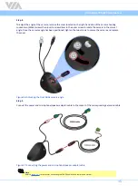
Страница 45: ...orrect angle Once the camera angle has been positioned tighten the two screws to secure the camera and replace the cover Figure 56 Adjusting the Front ADAS camera angle Step 5 Connect the power and microphone speaker adapter cable to the socket of the corresponding extension cable Figure 57 Connecting the power and microphone speaker adapter cable Note Refer to section 4 4 for details for connecti...
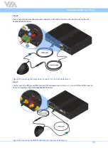
Страница 46: ...f the VIA Mobile360 M820 system Figure 58 Connecting the 2 pole power connector for the Front ADAS camera Step 7 Finally insert the MIC green GND yellow HP orange wires to ports no 1 3 and 5 of the HP MIC port on the rear I O panel of the VIA Mobile360 M820 system Figure 59 Connecting the HP MIC GND wires for the Front ADAS camera ...

Страница 47: ...hol to ensure the surface is free of grit and debris Step 2 There are two options to secure the DMS camera within the cabin of the vehicle Option A Remove the double sided adhesive tape protective cover then fix it securely by pressing the camera housing to the target location Figure 60 Removing the double sided adhesive tape protective cover Option B Place the DMS camera mount on the desired inst...

Страница 48: ...our vehicle Step 3 To adjust the angle of the camera loosen the hex screw located on the right hand side of the camera chassis with a 2 5mm Allen key Once the camera angle has been positioned tighten the hex screw to secure the camera Figure 62 Adjusting the DMS camera angle ...

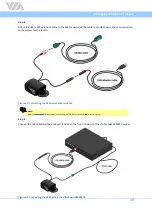
Страница 49: ... to the system for the IR LEDs Figure 63 Connecting the USB power adapter cable Note Refer to section 4 4 for details for connecting the FAKRA cable to the camera and system Step 5 Connect the USB cable to either USB port located on the front I O panel of the VIA Mobile360 M820 system Figure 64 Connecting the USB cable to the VIA Mobile360 M820 ...

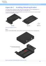
Страница 50: ...of a top casing a base cover and four M6 nuts Using the mounting bracket the VIA Mobile360 M820 can be installed on the side panel of a vehicle floor bed or any flat surface suitable for mounting Figure 65 Mounting bracket parts Step 1 Flip over the VIA Mobile360 M820 Install it onto the top casing of the bracket as shown in the figure below Figure 66 Installing the VIA Mobile360 M820 onto the top...

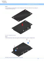
Страница 51: ... the base cover with the screw holes on the top casing and then gently install the base cover Figure 67 Installing the base cover Step 3 Secure the top casing and base cover together with the four M6 nuts as shown in the figure below Figure 68 Securing the top casing and base cover together ...

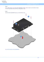
Страница 52: ...e to mount the VIA Mobile360 M820 Drill four holes and make sure the distance between the holes are perfectly matched with the mounting bracket s holes Step 5 Install the VIA Mobile360 M820 and secure it with M8 four screws Figure 69 Mounting the VIA Mobile360 M820 ...

Страница 53: ...10 687 4654 Email embedded viatech com Email embedded via tech eu Taiwan Headquarters USA Europe Tsinghua Science Park Bldg 7 No 1 Zongguancun East Road Haidian Dist Beijing 100084 China Tel 86 10 59852288 Fax 86 10 59852299 Email embedded viatech com cn 3 15 7 Ebisu MT Bldg 6F Higashi Shibuya ku Tokyo 150 0011 Japan Tel 81 3 5466 1637 Fax 81 3 5466 1638 Email embedded viatech co jp China Japan ...

Отзывы: